How I built a motorized sun tracker for my solar panels
One of my more complex projects
This is my home-made solar panel sun tracker. It is based on a 1960s vintage TV antenna rotator, driven by 21st century microcontroller technology.
It was pretty easy to build. This web site shows how I did it.
I had seen other solar panel tracking systems on the web based on antenna rotators. It looked like a neat solution to the problem of how to move
solar panels. Then one day I saw an older style, but brand-new, still in the box, antenna rotator for sale at a yard sale for $15, I snapped it up and got to work.
This is one of my more ambitious and complicated projects. Unfortunately, I have to include the usual disclaimer that I won't be able to give people
trying to build one of these much in the way of individual attention. My inbox gets flooded with questions and requests for help every day, and there
is just no way I can help everyone, or even most people. You'll need to have a decent grasp of mechanics, electronics and programming to duplicate
this project. If you don't have them, well I am not going to be able to teach it all to you. Basically, you are going to be pretty much on your own. I will be
continually updating this web site with answers to frequently asked questions as time goes on. So if you don't get a response to a question, check back
from time to time. If a lot of people are asking the same thing, I will address it here.
Don't feel you need to copy every part exactly. Feel free to innovate, experiment, and substitute. There is a lot of wiggle room in the design. Lots of
things can be changed or modified and a working tracker would result. There are must be dozens of different ways to implement the electronics alone.
You could use an Arduino, a Raspberry Pi, a PC, or a handful of analog components, instead of an MBED, to implement the sun tracking electronics.
This is just the way I did it. I hope it sparks some people's imagination and ambition. Email me with details on how you do it and I'll add a link to your site.
Here is some time-lapse video of the home-made solar panel sun tracker in operation. In the video it is set up on my remote Arizona property, and is
doing a good job of keeping my solar panels pointed at the sun.
Why build a tracking platform for my solar panels? Solar panels produce a lot more power if they are pointed directly at the sun all the time than they do
in a fixed position. I got tired of manually moving my panels to keep them pointed at the sun throughout the course of the day. If I wasn't around to move
them every few hours, they wouldn't make enough power to keep my batteries fully charged. I decided to automate the process and free myself from having
to manually move the panels.
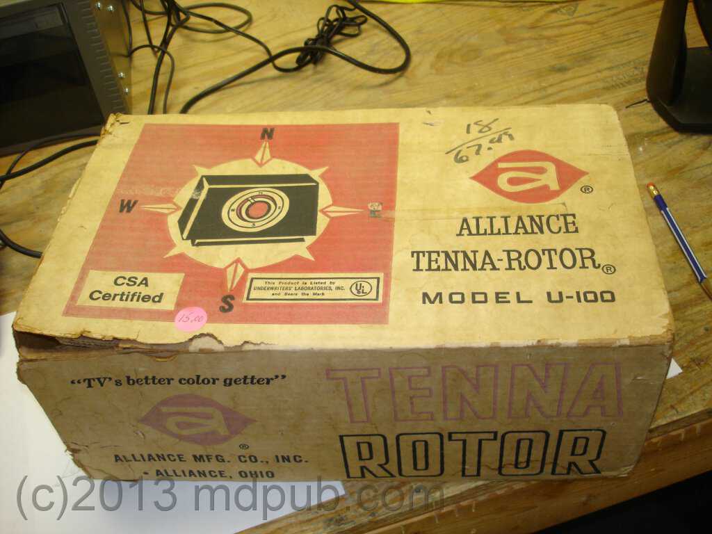
Here is the box the antenna rotator came in. It still has the $15 yard sale price tag on it. The box is beat up and faded from being
in storage for so long, but the unit inside was still brand new and wrapped in the original plastic.
It is an older unit, based on 1960s technology. The person had purchased the unit new, but never used it. It had been sitting in a
box in their garage for decades until they finally decided to get rid of it at the yard sale.
The trackers I saw online were based on newer units, but I immediately saw how to make this older one
work as a solar tracker. Basically I just threw away almost all the electronics that originally drove the unit, kept just the actual
motor drive, and rolled my own control system. I'll go more into detail about the electronics below. Older units like this are fairly
easy to come by and inexpensive at places like hamfests and on Ebay, and of course yard sales. Here is a link to the manual for this
particular model: http://w5jgv.com/downloads/U-100_Manual.pdf.
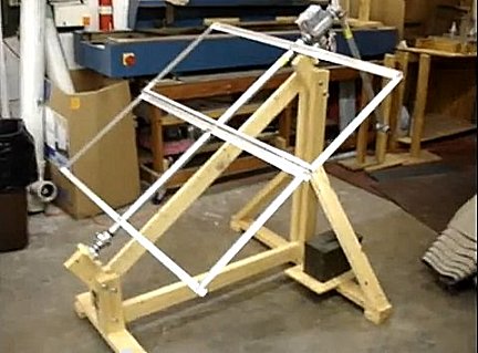
The first step was to come up with a way mount the drive motor and solar panel(s). I did a little back of the envelope brainstorming and
designed a mount for the tracking system that was simple, inexpensive, and easily broken down for transport. It is made mostly from 2X4s
and standard pipe fittings, and is held together with carriage bolts.
This unit was designed to be portable, since I would be building it in my workshop in Florida and then transporting it to Arizona for use.
I designed it to be easily knocked down and packed for transport, and easily re-assembled in the field with only a few tools. The core unit
consists of just five main structural parts. There is the north support, the south support, the rotating assembly, and two braces to hold
everything together.
When set up in the field, the base unit would be leveled in both the east-west axis, and the north-south axis, and aligned toward due
north. Note that magnetic north and due north can be quite different directions in some parts of the world. Apply your local deviation
when using a compass to align the unit.
Here is a photo of the north side support of the solar tracker. It measures 48 inches wide at the base and stands 43 1/2 inches tall.
Keep in mind that these dimensions are only correct for use at 34.6 degrees north latitude. If you are significantly further north
or south, you will need to modify the dimensions of this piece. More on that below. The support is made of 2X4s that are screwed and
glued together. Note that there are two little feet on the bottom. They aid in levelling the unit when setting it up. The gap between
the upright 2X4s is exactly the thickness of another 2X4, or about 1 1/2 inches.
Here is a photo of the south side support of the solar tracker. It measures 24 inches wide and stands 13 1/2 inches tall. It too
is made from 2X4s glued and screwed together. This piece also has little feet to aid in levelling the entire unit when setting it
up. This piece is probably more or less universal, and will work for a wide variety of latitudes. Again, the gap between
the upright 2X4s is exactly the thickness of another 2X4, or about 1 1/2 inches.
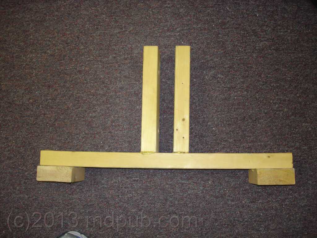
The horizontal 2X4 brace that goes from the bottom of the north support to the bottom of the south support is 48 inches long. It fits
between the uprights and gets bolted through them. This is another piece that will have to be sized for your particular latitude, since
the distance between the north and south supports will change as the angle of the driven pipe changes.
The diagonal brace is a piece of 1X4. It was added to take the bulk of the stress off of the rotating assembly so it doesn't bind up.
It slips on the bolts holding the rotating assembly in place.
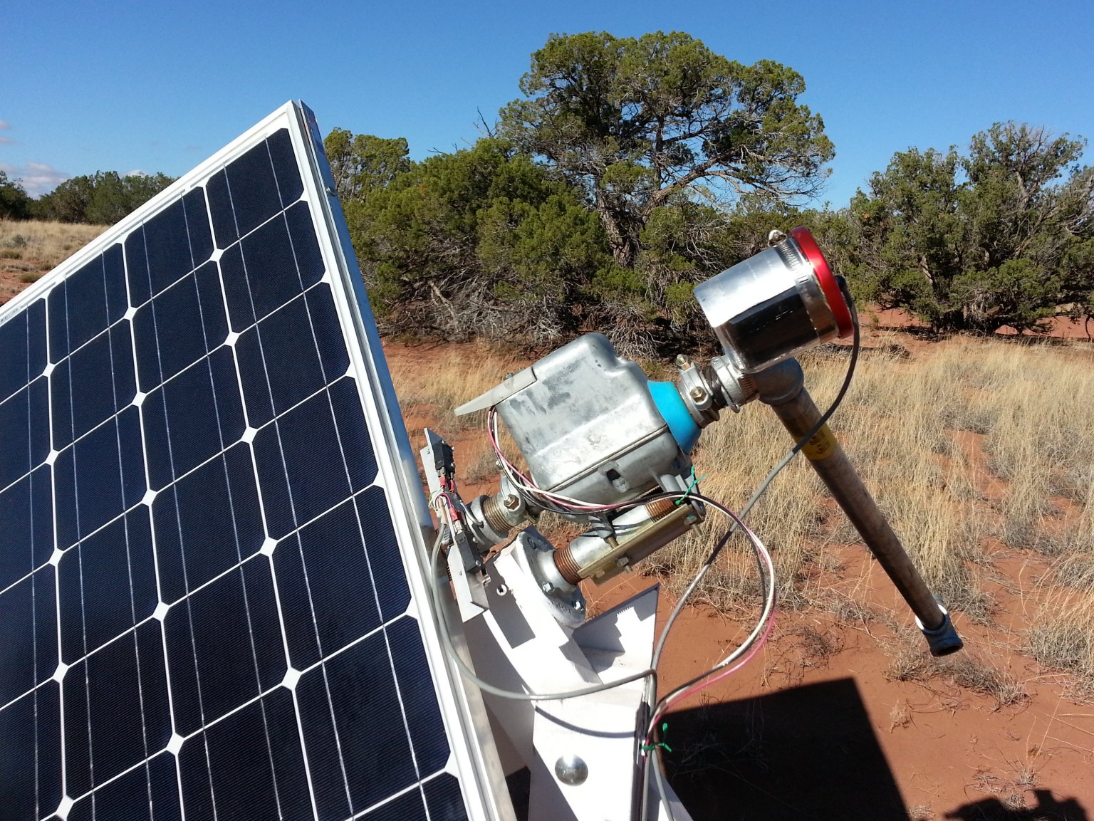
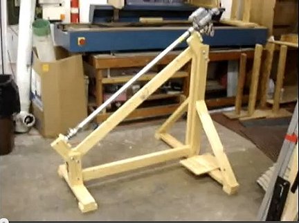
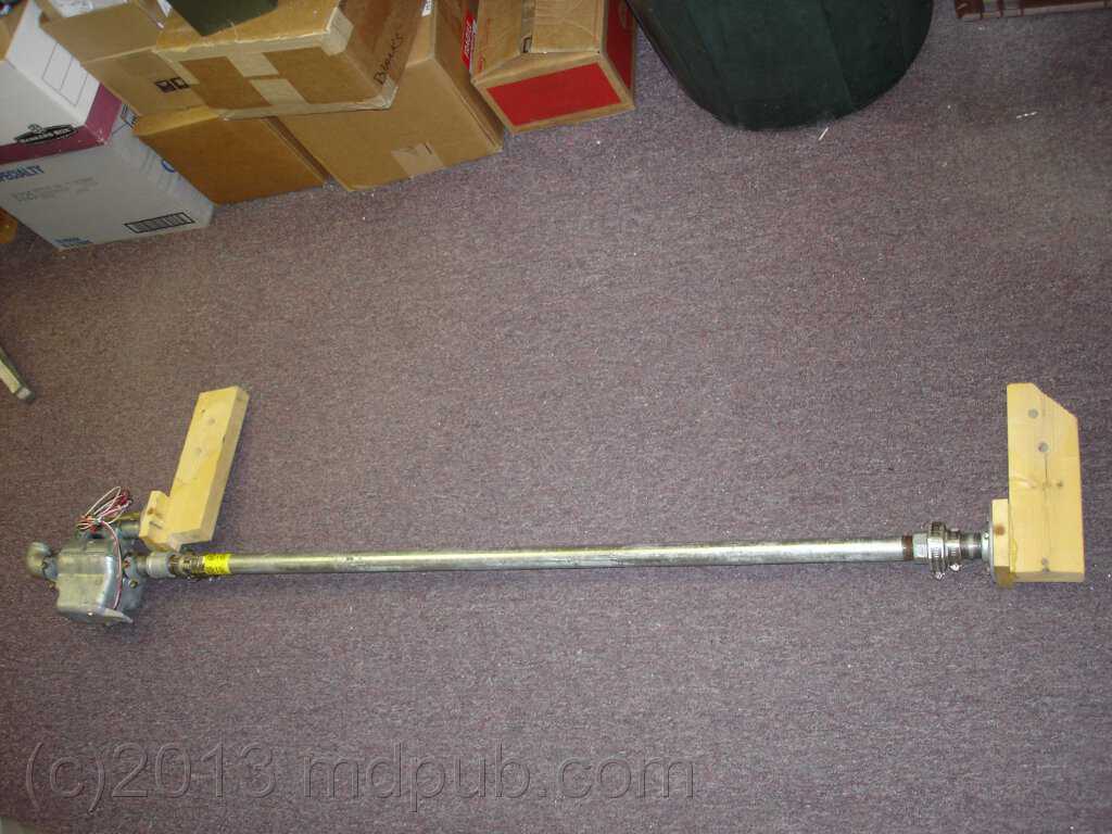
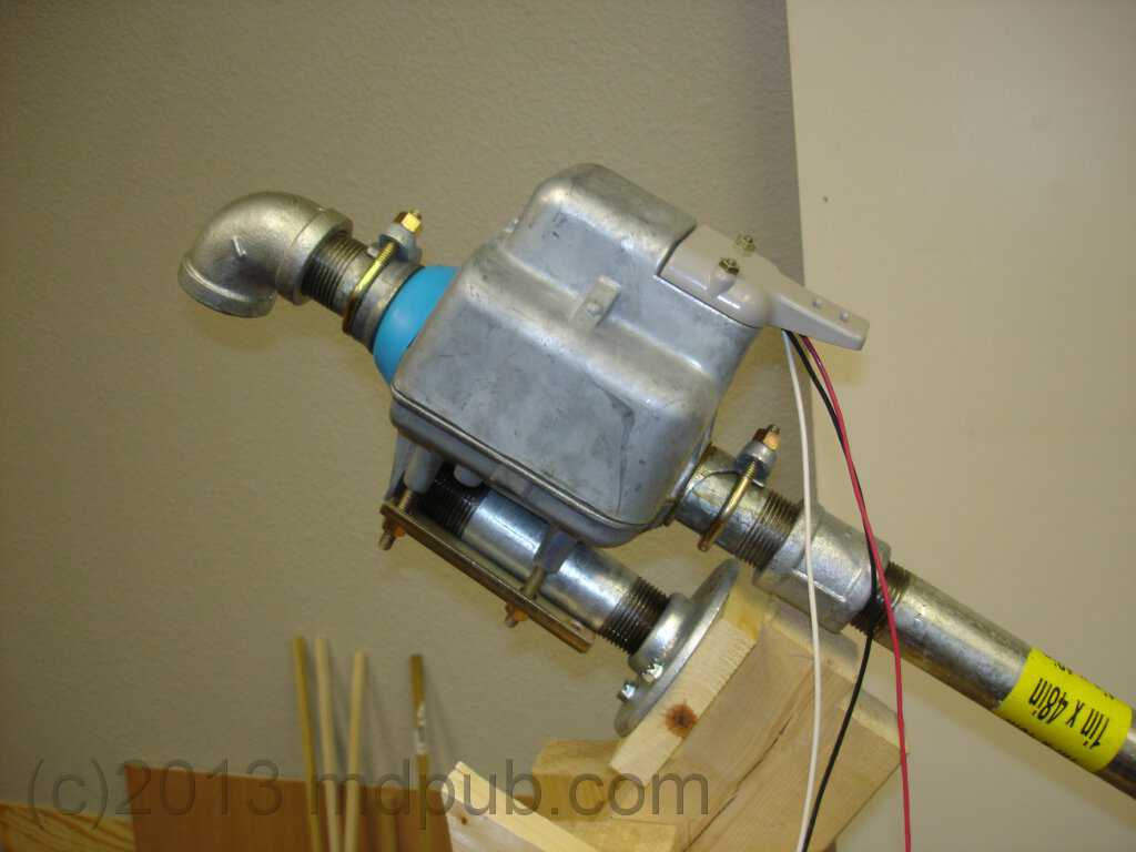
Here is the heart of the tracker unit. This is the drive motor and rotating assembly. The antenna rotator drive motor is at the left, with its
associated mounting structure. A 4 foot long, 1 inch steel pipe is driven by the rotator, and will carry the solar panels. A bearing and
mounting structure are at the right end. Details below.
Here is a close-up of the motor end. The antenna rotator is designed to be clamped onto a fixed mast, and rotate a shorter mast with
an antenna attached to it. So I created a pseudo fixed mast to clamp it to. The short piece of 1 inch pipe at the top (under the coil of wire)
serves as the mounting point for the rotator. The short piece of pipe screws into a floor flange, which in turn is bolted to a 3 1/2 X 3 1/2
square piece of wood that is glued and screwed to a 12 inch long piece of 2X4. The 2X4 slips between the uprights on the north support and
gets bolted in place.
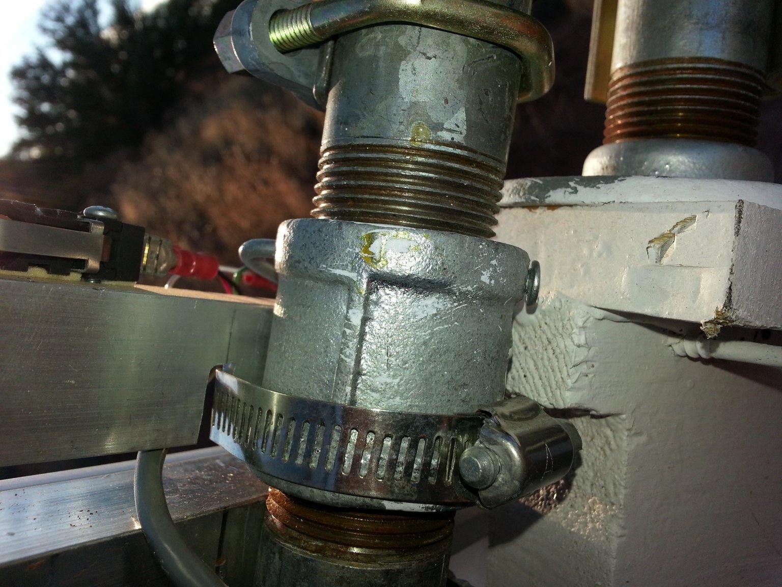
Another short piece of 1 inch pipe passes through hollow drive shaft of the rotator and gets clamped in place. A 90 degree elbow is screwed on
to the left (top) side of this short shaft. A 4 foot long piece of 1 inch pipe is connected to the other end via a coupler.
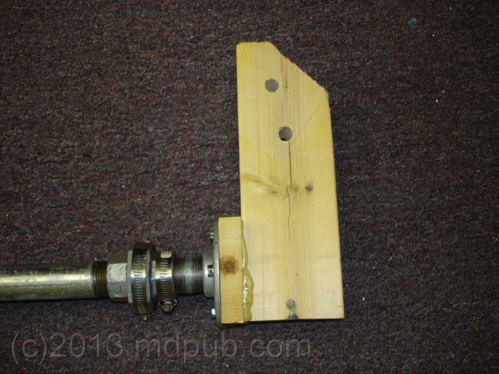
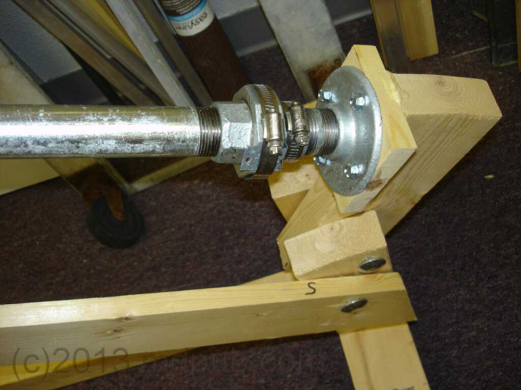
Here is a close-up of the bearing end. The lower end of the 4 foot long pipe that carries the solar panels screws into a union that has been modified to serve
as a bearing (more on that below). A close nipple connects the other side of the union to another floor flange. The floor flange is bolted
to another wooden mounting structure identical to the one at the other end, but one corner was cut off to prevent it from interfering with the lower
brace holding the north and south supports together.
The first time I assembled the unit, I held all the pieces together with large c-clamps. Once I got the angle of the drive axis correct and
everything nice and squared up, the clamps were tightened down to hold it that way. Then I drilled holes for long carriage bolts to bolt
everything together.
I should talk a little about how I determined the angle to use on the north-south rotational axis of the tracker. I planned on using this tracker
on my remote, off-grid property in Arizona. So I designed it to work at the latitude of my property.
The unit is fixed in latitude. I didn't make it adjustable. It will only be the correct angle during Spring and Autumn, but those are
the times of year I am usually on my property. It will be close the rest of the year. It will be a little high in Summer, and a little
low in Winter. Still, it will work much better than fixed panels.
The angle of the with respect to the ground of the axis of rotation is set to be the same as the latitude of location where the tracker will be used.
Think about it this way to visualize why. If it was used at the Equator, 0 latitude, the angle with respect to the ground would be 0, so the axis
would be horizontal. If used at one of the poles, +90 or -90 latitude, the angle with respect to the ground would be vertical. So it follows that
the correct angle is always the latitude of the location where the tracker will be set up. My Arizona property is at about 34.6 Degrees North Latitude,
so that is the angle I used. The angle you need will depend on where you are. Not only will your angle probably be different, but the dimensions
of your base structure will also be different. The dimensions of the base will depend on the angle you use. Assuming
you use the same south support, the height of your north side and the distance between your south and north supports can be calculated with a little
trigonometry.
This angle is not always correct. If the sun always rose due East and set due West it would be perfect. However, the Earth is tilted 22.5 degrees
on its axis. So during the course of the year the sun seems to move 22.5 degrees North in Summer, and 22.5 degrees South in winter (this is
reversed in the Southern hemisphere). So this fixed angle is really only ideal during the times of year when the sun seems to rise roughly
due East and set roughly due West. This would be during Spring and Autumn, which just happens to be the times of year I am on my property.
An adjustable version could be easily created that could be set to a lower angle in Summer and a higher angle in Winter. For now though I will
leave that as an exercise for the reader, because it works fine for me as is.
Here is another view of how the rotator head is mounted. I don't draw actual blueprints for the stuff I build. So don't bother writing and
asking for them. I tend to just visualize stuff in my head and then build it without bothering with the intermediate step of drawing up plans.
I know this makes it difficult for others wanting to reproduce my work, sorry. If you live at a different latitude than me, you are going to have to
modify the design anyway. So there isn't much point in my being too specific about dimensions anyway. But I'll take lots of pictures and post them here. People with
the knack for building things should be able to figure it out from the photos and a few dimensions. If you are having trouble figuring out something,
write and ask a question. I will get back to you with info, advice, dimensions, and/or more photos as time allows. If I find a lot of people asking
the same question, I will put the answer here on the web site.
This photo shows how the lower bearing end of the drive pipe fits into the south side support and gets bolted into place with
carriage bolts. The other end is similarly attached to the north side support. The lower end of the diagonal brace is also visible.
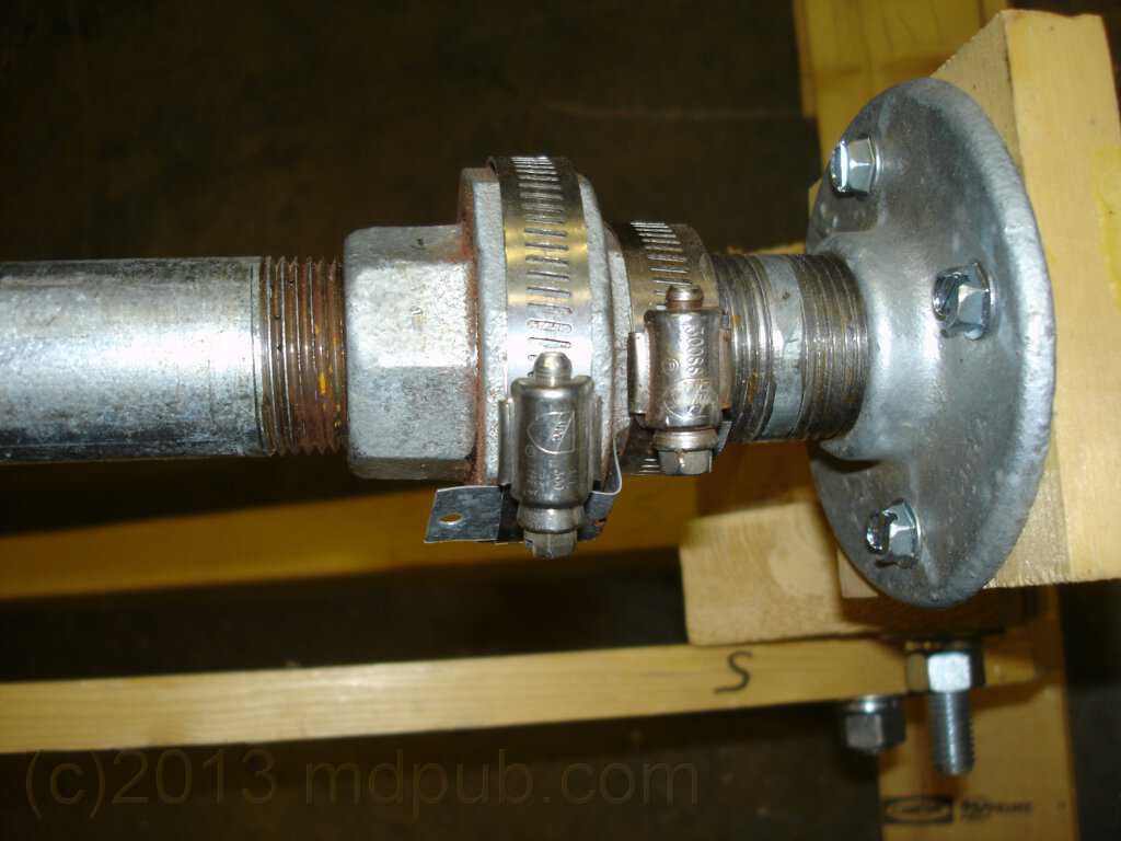
Here is a close-up of how the union has been converted into a bearing. This is an old amateur astronomer's trick for building telescope
mounts using pipe fittings. I'm an old amateur astronomer, so I used it here. It works great and is dirt cheap.
Basically, the union is just packed with grease, and not tightened all the way. This allows it to serve as a pretty good bearing, as seen in the video below.
To keep the union from loosening up and falling apart, or tightening up and seizing as it rotates, two hose clamps and a Z-shaped piece of metal are
used to hold the parts fixed with respect to each other. In this photo you can just see the Z-shaped piece of metal going under and between the two hose clamps.
Here is a brief video showing how a pipe union can be used as a bearing. The hose clamps and z-shaped piece of metal are not yet installed.
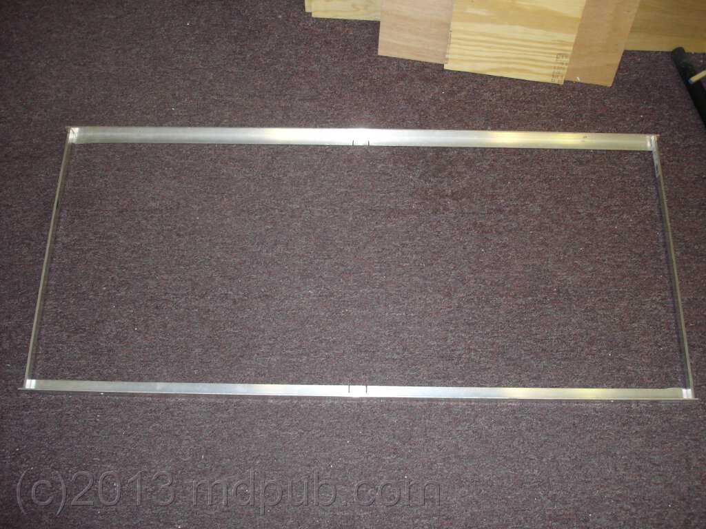
This photo shows one of the aluminum frames that hold the solar panels. It is made from aluminum angle. This particular frame holds a 100W panel,
and measures 47 1/8 by 21 1/2 inches inside dimensions. Basically, it is just slightly larger than the outside dimensions of the solar panel.
The panel drops right into the frame, and will be held in place with screws that go through the frame into the sides of the panel.
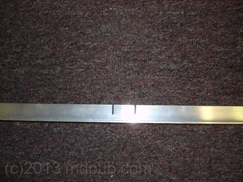
Notches cut in the frame for mounting on the tracker drive pipe are just visible in the photo. Click the photo for a larger version.
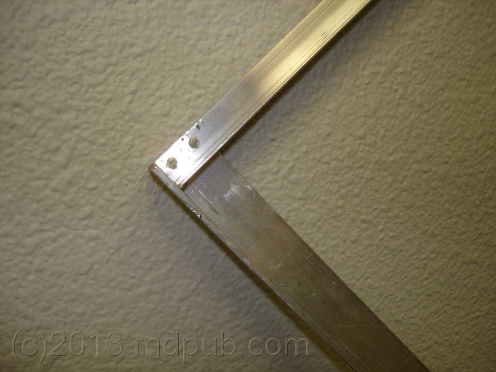
This photo shows how the aluminum angles are butted and screwed together at the corners. I didn't have time to get fancy. I only spent about
an hour tops building my frames, but they work great. If you have the time and skills, feel free to miter and MIG/TIG weld the corners.
Here is a close-up of the notches cut in the frame for mounting on the tracker drive pipe. The notches are the same depth as the hose clamps used
for mounting are wide.
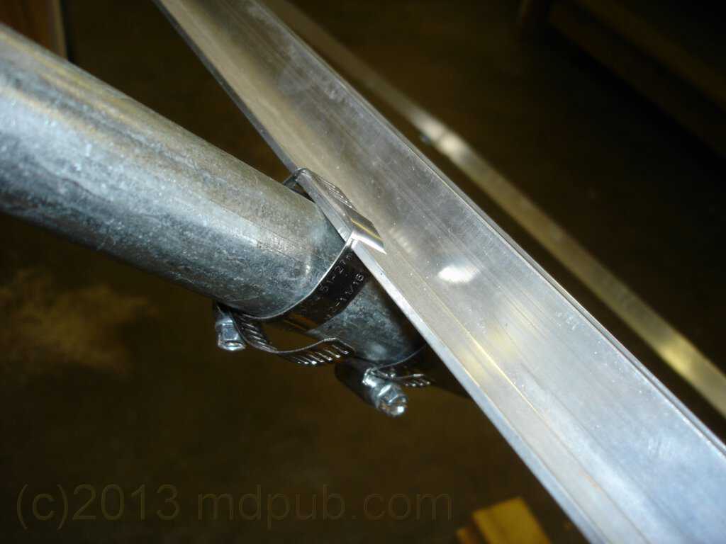
Here is a close-up detail shot of how the hose clamps are used to mount the frames on the tracker drive pipe. Tightening down the hose clamps
really locks the frames onto the pipe quite tightly. I was somewhat surprised at how well it worked.
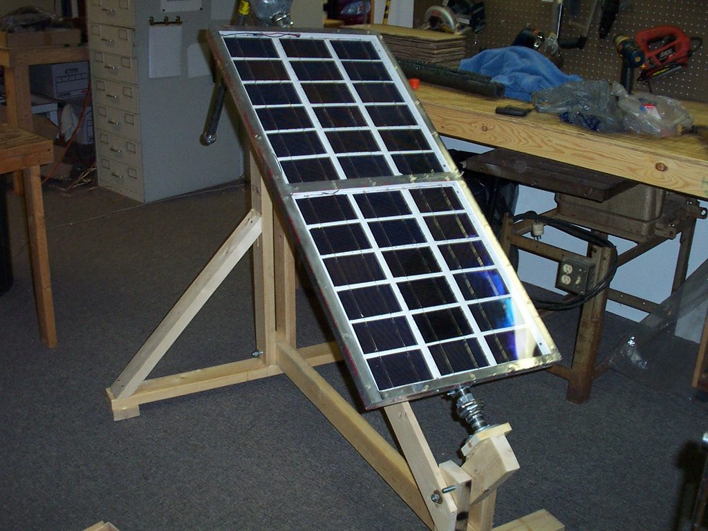
During initial indoor testing I only mounted one solar panel length-wise on the tracker, taking up the whole drive pipe. My intention all along though was to
eventually mount two panels. The motor seemed to have plenty of torque, and with counter-weighting, I was confident it could handle two panels. If you only
have or need one panel, this is a way to mount it.
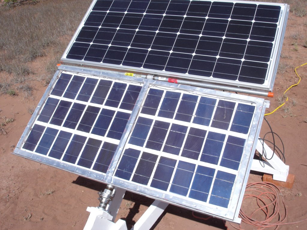
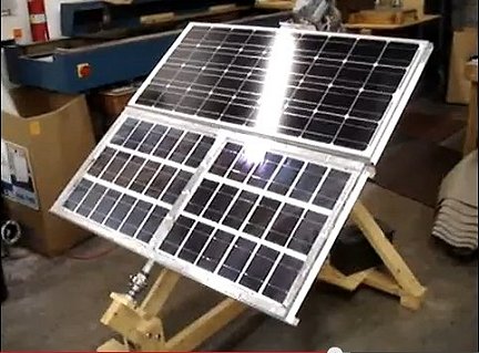
This photo shows two aluminum frames for holding panels clamped onto the drive pipe. By turning the panels 90 degrees, two will now fit. The frames
are slightly different sizes because the panels they will be holding are slightly different.
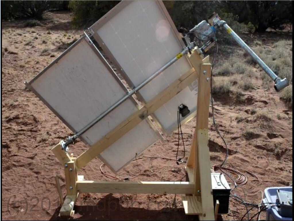
This photo shows the two solar panels in place. The panels just drop right into the frames, which have been made slightly larger than the outside
dimensions of the panels. Screws hold the panels in place so the wind can't blow them out of the frames.
The top panel is a commercially made 100 Watt unit I bought because I got a really good deal on it. The bottom panel is one of
my home-made 60 Watt solar panels. Follow the link to see how I make them.
160 Watts may not seem like a lot of power, but my power needs at my cabin are minimal. With the tracker keeping the panels pointed at the
sun, and my home-built wind turbine to supplement their output, my batteries stay
charged and I have plenty of power.
This photo shows the counterweight pipe. It is a piece of 1 inch steel pipe 30 inches long. It gets screwed into the elbow at the top end
of the motor unit. The pipe alone is a little more counterweight than is needed for one panel. For two panels I added a steel T fitting at
the end of the pipe. The antenna rotator was designed to move a balanced vertical mast. The counterweight is necessary to reduce the amount
of torque the motor has to exert to move the panels which are hung off the side of a nearly horizontal mast. Your panels will probably
have a different weight than mine and need a different counterweight arrangement. Experiment with different lengths of pipe, and/or extra
fittings to get the balance as close to perfect as possible and prevent burning out the motor or stripping the gears.
Here is a video walk-through of assembling the solar tracker with detailed explanation of all the parts and how they go together.
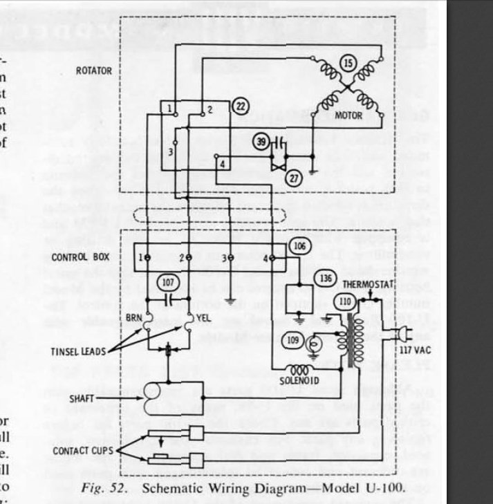
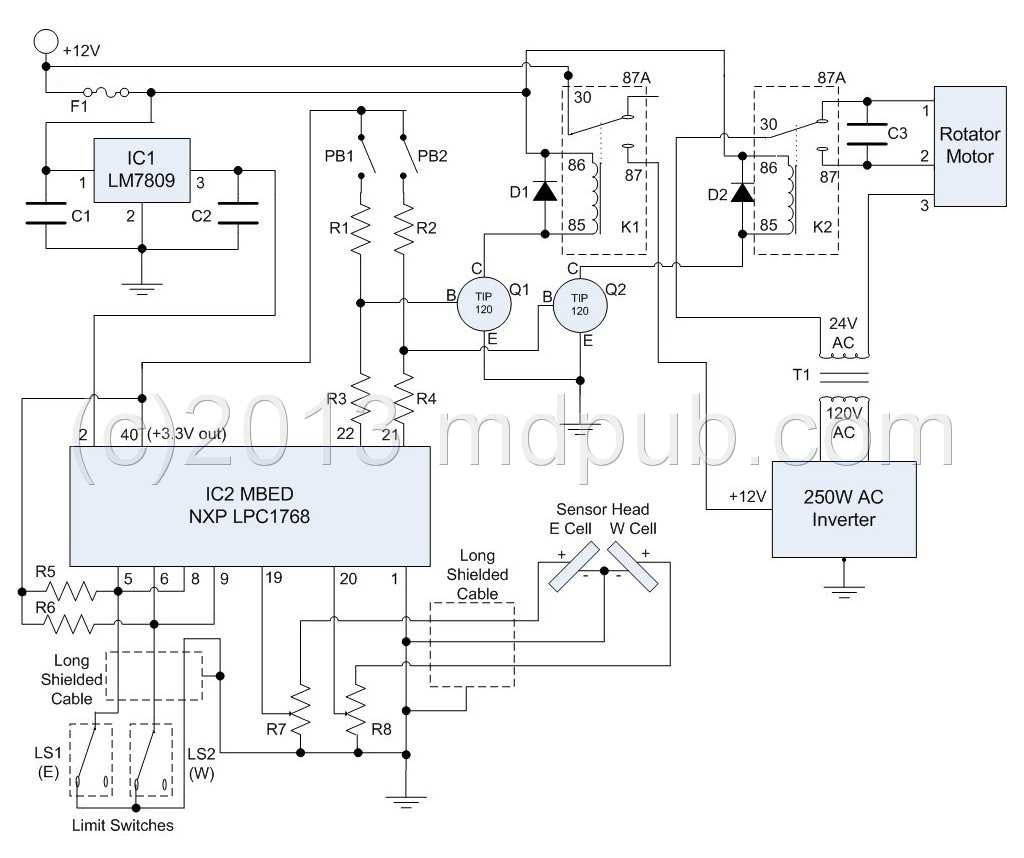
Here is the original schematic for the antenna rotator. It is totally electro-mechanical. Very old-school, almost primitive. On the other hand, it
still worked after decades of storage. One of the quirks of this old unit is that the motor in the rotator head runs on 24V AC. That made designing
a new control system for it challenging. I looked for ways to modify or automate the original control box, but couldn't figure out a way to make it work.
So I gave up on trying to use the old control box, stripped it of usable parts, and started designing something completely new.
I didn't re-use many of these parts. The actual rotator head is of course used. But from the control box I
only kept the 120V to 24V transformer (#110), and the motor capacitor (#107). The rest got junked. In the end, I decided to use a different transformer
too. The one inside the original controller looked very wimpy to me, so I substituted a more robust one. I figured that the antenna rotator wouldn't have
been moved very often when used for its original application. The way I am using it though it moves a lot, every day. So the wimpy transformer worried me. It
may have been overkill, but I already had a bigger transformer rattling around in my junk box, and I won't ever have to worry about it, so why not?
Here is a schematic of the controller electronics I came up with after several iterations. Click the image for a larger view. the circuit
is based on the MBED rapid prototyping platform. The
MBED is basically a complete computer on a tiny module. It can be programmed in C using an online IDE. The MBED is quite powerful, has lots of IO capability and
just about every bell and whistle anyone could want. It is really overkill for this project, but I was familiar with MBEDs from using them in
projects at work. So it was my first choice for this project. You could easily substitute an Arduino, a Raspberry Pi, a PC, or a handful of
analog components to do the same thing. This is just the way I did it. Feel free to roll your own.
The heart of the circuit is the MBED. It reads the voltage value (via two of its analog inputs) from two small solar cells mounted at right angles
to each other. The motor of the antenna rotator is moved so as the keep the voltage from the two solar cells nearly equal by keeping them pointed
at the sun.
The motor is energized by closing a relay and turning on an AC inverter. The output of the inverter is stepped down to 24V AC with a transformer.
The direction of the motor is controlled with another relay. I used 40 Amp automotive relays because they are cheap, available everywhere, and I
already had a few on hand. The relays are energized by TIP120 Darlington power transistors driven by output
lines from the MBED. Two push buttons were added to manually move the motor for testing and troubleshooting. Pressing PB1 moves the motor west.
Pushing PB1 and PB2 together moves the motor east.
Two limit switches are read using MBED input lines. Motion only starts in a given direction if that limit switch is closed. Motion is stopped
via an interrupt if the limit switches open at the limits of travel.
A LM7809 positive 9V regulator provides stable power for the MBED from the 12V supply. The MBED is based on 3.3V logic, and has an on-board regulator and a 3.3V output
line that is used to tie pull-up resistors to.
Parts List
C1 - 0.33 uF
C2 - 0.1 uF
C3 - NPO (harvested from original control box)
D1-D2 - 1N4001 or equiv Diodes
ECell-WCell - Thin-Film Copper Indium di Selenide (CIS) Solar Cells
F1 - 2A Slow-Blow Fuse
IC1 - LM7809 +9V Voltage Regulator
IC2 - NXP LPC1768 MBED
K1-K2 - 40A SPDT Bosch Type Automotive Relays
LS1-LS2 - Momentary Contact NC Switches (see below)
PB1-PB2 - Momentary Contact NO Push Buttons
Q1-Q2 - TIP120 NPN Power Darlington Transistors
R1-R6 - 1k 1/8W Resistors
R7-R8 - 10K Trimpots
T1 - 120VAC to 24VAC 2A Step-down Transformer
AC Inverter - 200-250 Watt 12V DC to 120V AC Power Inverter
The code (software) for this project can be found at http://mbed.org/users/omegageek64/code/suntracker/.
It is a fairly simple program.
As I said above, the MBED is overkill for this project. However its untapped potential could allow for adding more features and functions in the future.
A second motorized axis could easily be controlled. Battery management, charge control and temperature compensation could be added. Logging of power
production and usage data could be added. The sky is the limit. Let your imagination and ingenuity run wild.
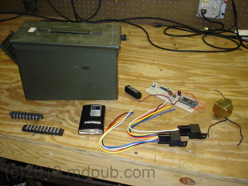
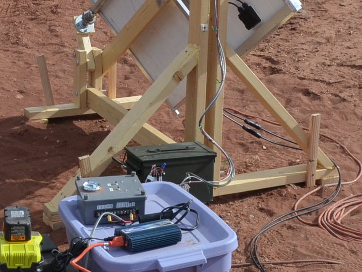
The electronics for driving the unit are housed in an old ammo box that I got at a yardsale for $5. It makes a perfect enclosure. It is rugged,
weather-proof, and plenty roomy. The box holds two 40 Amp automotive relays, a power inverter, a 120V to 24V step-down transformer, the
breadboard containing the actual drive logic, a fuse holder, and terminal blocks for wiring everything together, There are feed-through
terminal blocks mounted to the outside of the ammo box so that various signal and power connections can get into and out of the box.
This photo was taken very early on in the project. The breadboard has an earlier version of the electronics on it.
The small 100W inverter shown in the photo was later replaced with a more robust unit.
I tend to err on the side of robustness. The little inverter worked, but it was straining, and I figured it was a weak point that would fail
eventually. So I bought a larger 250W unit. The motor moves faster and smoother with the bigger inverter, and the inverter doesn't make
strange noises like a dying animal.
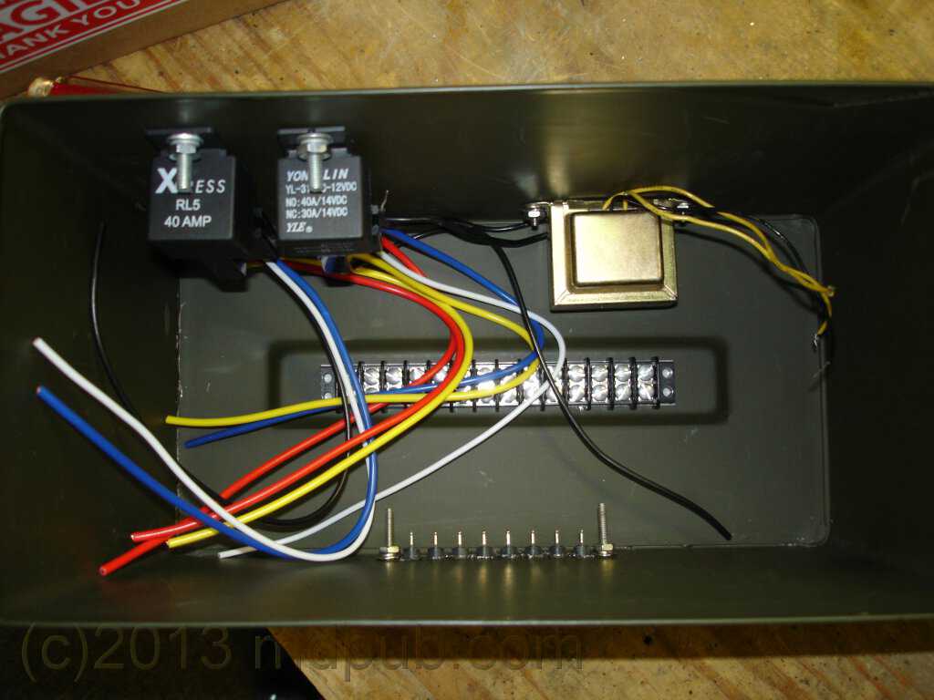
Here I have begun mounting parts inside the ammo box. The relays, transformer, terminal strip and one of the feed-through terminal strips have
been mounted.
Though it looks like the electronics were the last thing to be done from its position on this web page, they actually were one of the first
things I started work on after acquiring the antenna rotator. The electronics went through several different versions before settling on this
final design.
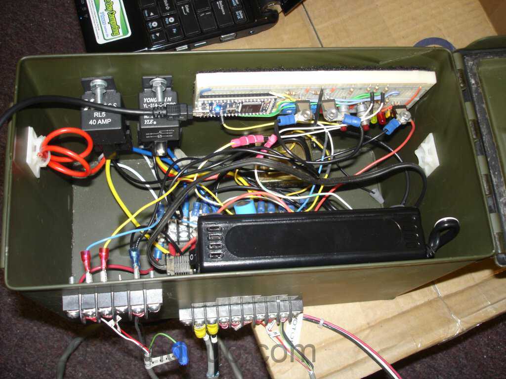
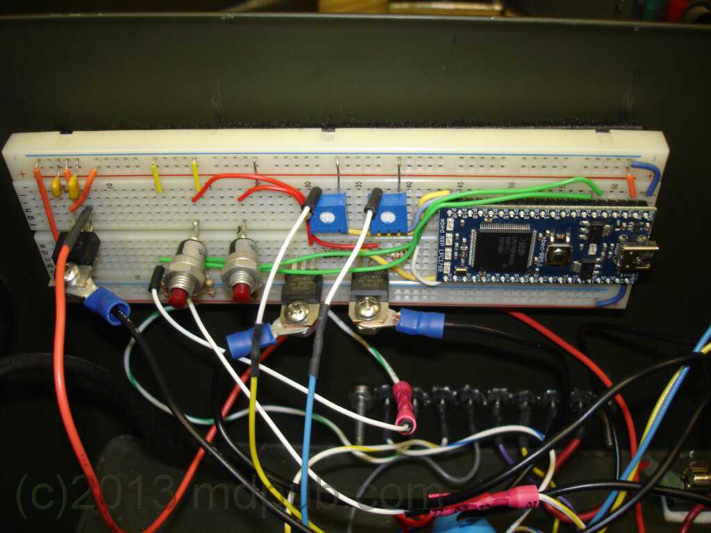
Here is a view inside the ammo box with all the electronics installed. The white breadboard with all the logic is on the upper right.
The long black rectangle is the power inverter. The breadboard and inverter are held in place with industrial strength velcro. A second
pass-through terminal strip has been mounted at the lower left. Everything has
been wired together creating a real rat's nest effect in the bottom of the box.
Looking closely you will see that a USB cable is plugged into the MBED module on the breadboard and goes to my netbook computer just visible
at the top of the shot. This photo was taken during programming/testing/debugging of the drive electronics.
Here is a close-up of the breadboard with the "brains" of the system on it. The MBED computer module is on the right. Left of
the MBED are the two trimpots for adjusting the signals from the sensor head. Below them are the power transistors for driving the relays.
Further left are the manual override push buttons for moving the tracker manually. At the far left is the 9V voltage regulator.
The breadboard is temporary. Eventually I will build a proper circuit board and install it. I was in a big hurry to get the tracker up
and running before my last trip to Arizona, and there was much last-minute tinkering, so the breadboard was the way to go.
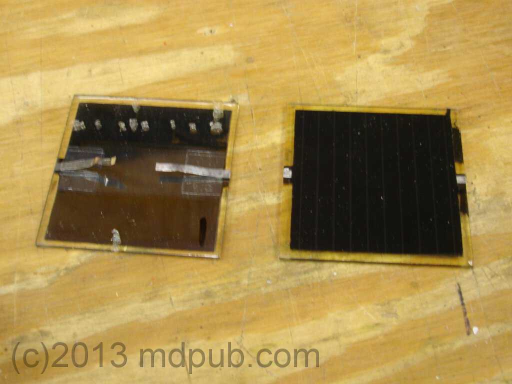
The sensor head consists of two small thin-film Copper Indium di Selenide (CIS) solar cells of the same type I used in
my home-made folding 15 watt solar panel. I had several of these
cells left over, so it seemed like a no-brainer to use them as sun sensors in the tracker.
The two small solar cells are mounted at 90 degrees with respect to each other. The idea was that one cell or the other would get more sun, and the tracker
would move until they were getting equal sun.
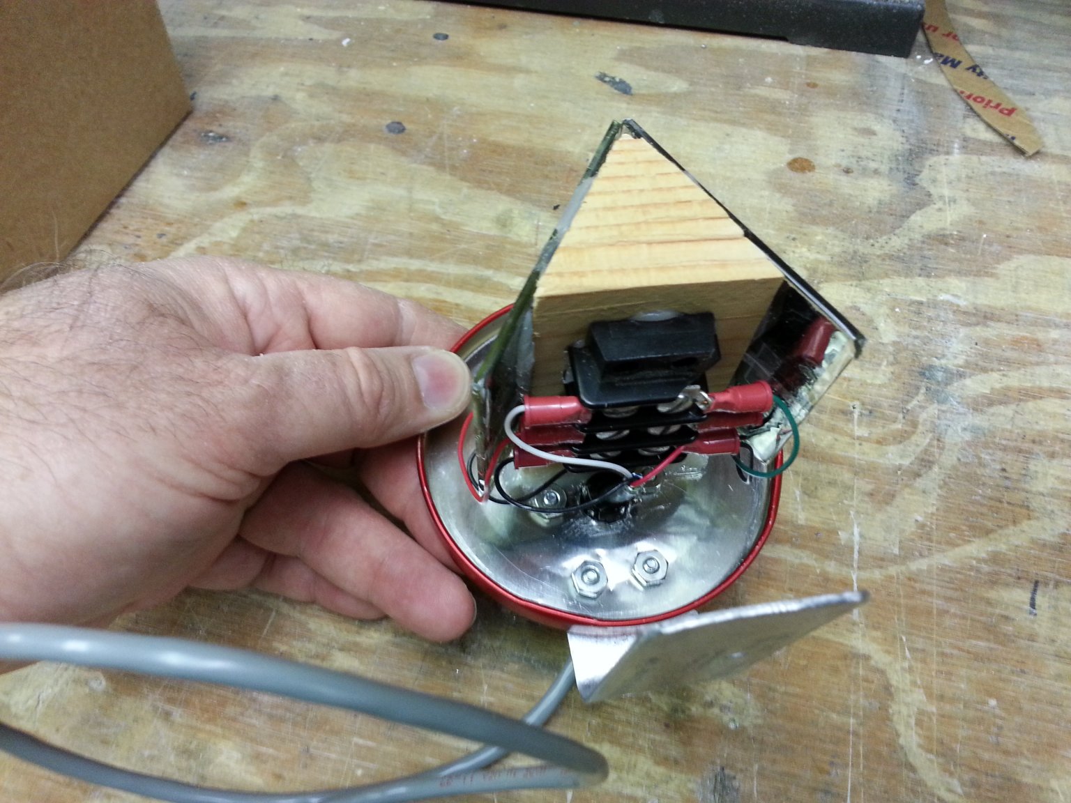
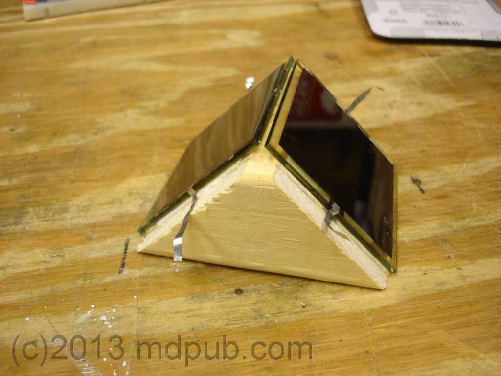
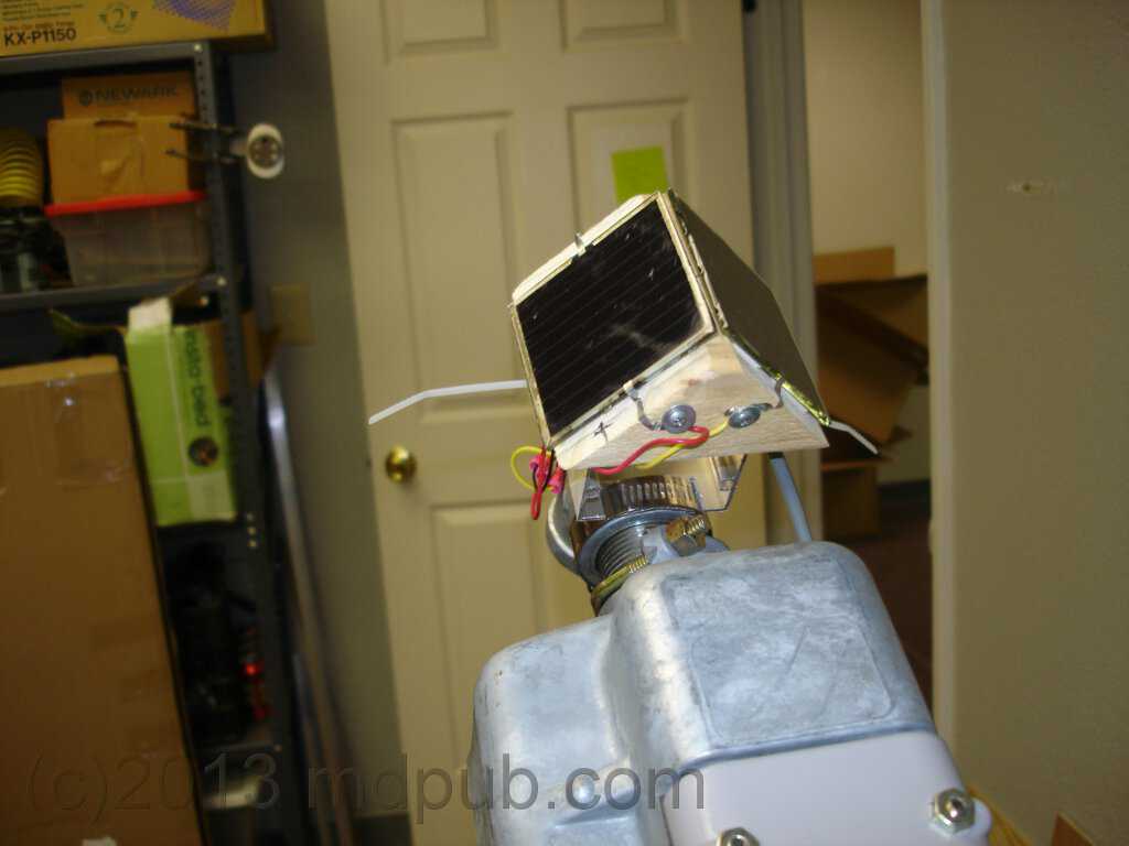
Here is a view of the completed sensor head. It is mounted on a short piece of square aluminum tubing, which in turn will be mounted on the drive
pipe of the tracker. I drew on some dimensions for those who are always asking me to include them. The sensor head is held on with a hose clamp in
the same way the panel frames and limit switch bar are attached.
Here is a view of the sensor head attached to the tracker. The sensor head is mounted on the stub of pipe coming out of the top of the rotator unit.
This keeps it out of the way when mounting the panels, and makes it less likely to be shaded by anything.
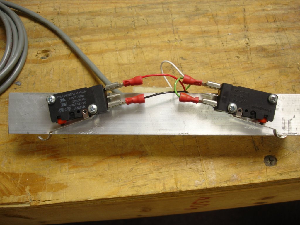
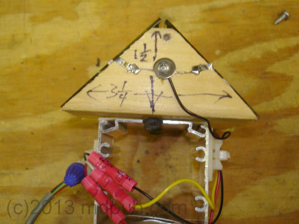
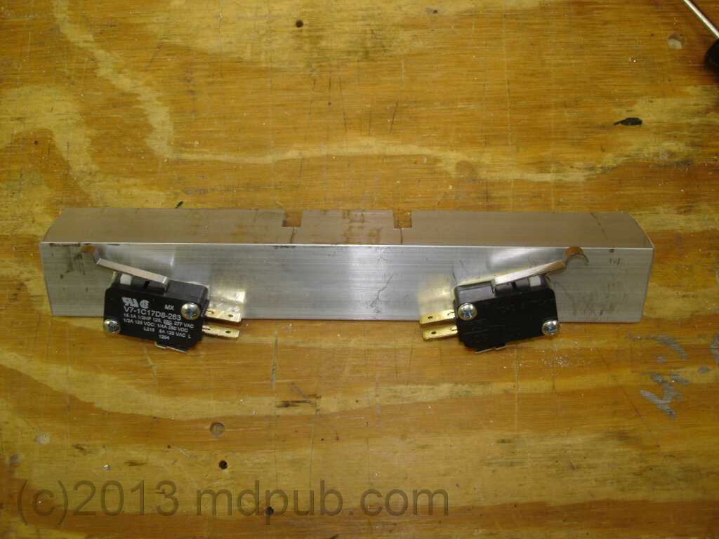
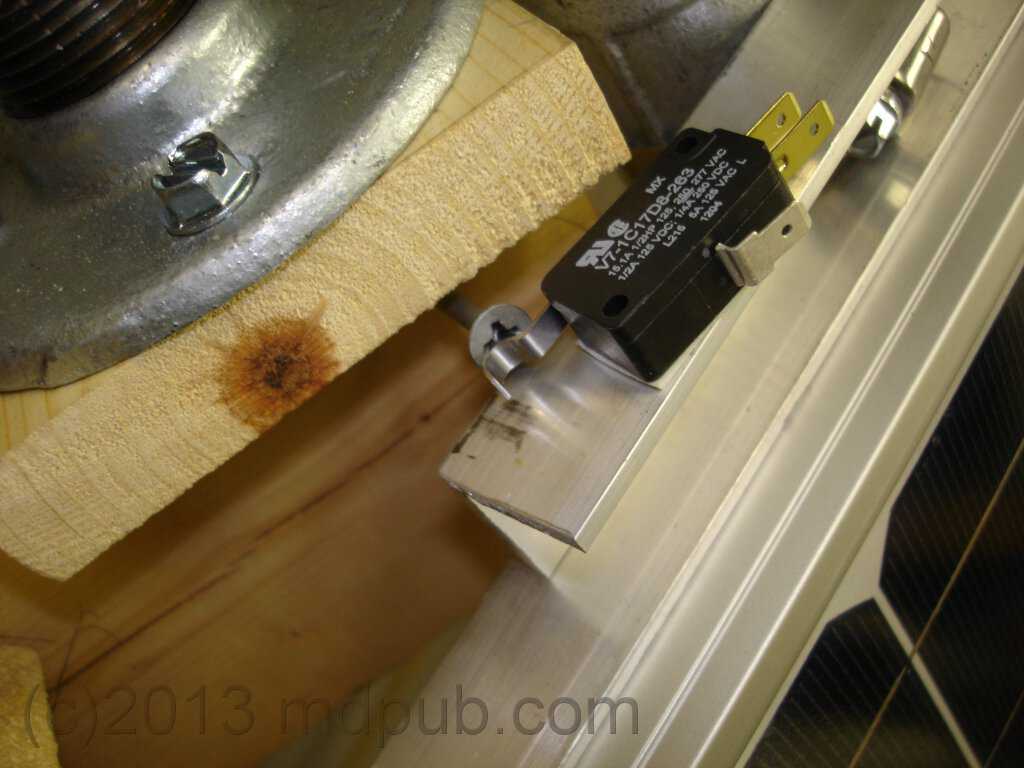
Two limit switches are mounted on a piece of aluminum angle held onto the drive pipe with a hose clamp in the same manner as the solar panel frames.
The paddles of the switches engage with the heads of long screws protruding from the wooden support structure for the drive motor. The
limit switches stop the motion of the motor at both the east and west ends of travel. The switches are wired normally closed, and open
when the limit of travel is reached.
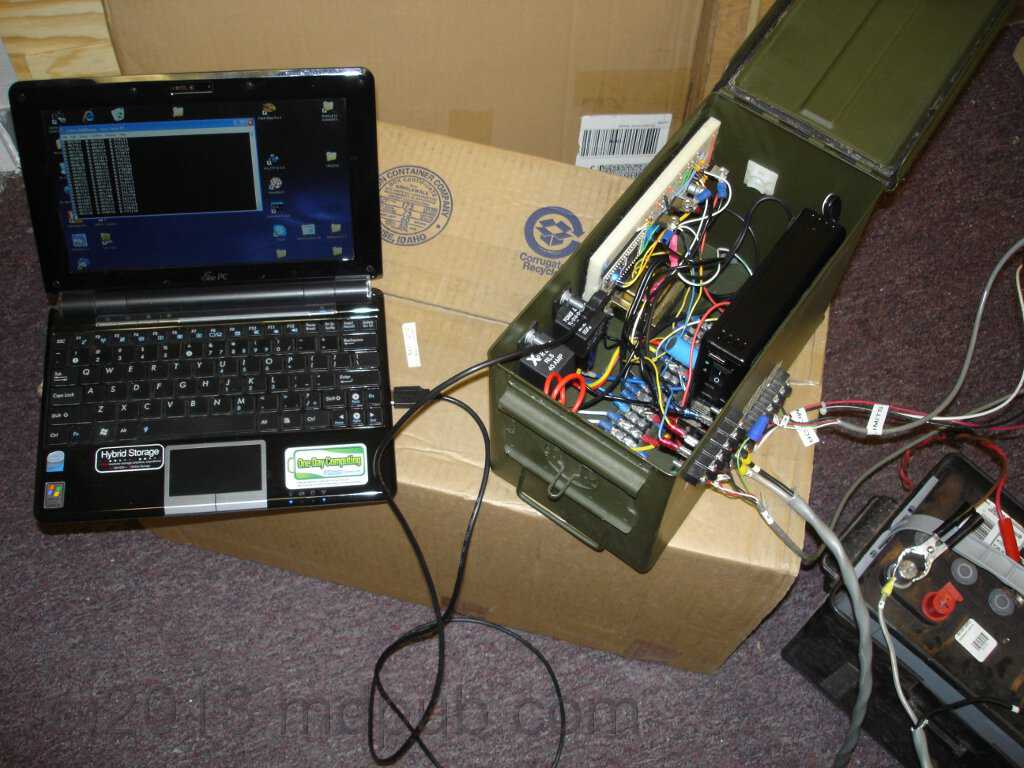
This photo was taken during a marathon testing and debugging session at my workshop the last weekend before leaving for Arizona. My netbook computer
is plugged into the MBED unit in the ammo box. A large, deep-cycle battery is powering the electronics and the tracker unit (not in the shot). I
needed to get the unit working, and then break it down and pack it for transport by Sunday night. It all came right down to the wire (doesn't it
always?). But it appeared to all be working well by Sunday afternoon. So I disassembled it all and packed it for shipping. Little did I know that there
was going to be a big problem when I got to Arizona.
Here is a photo from the above testing and debugging session.
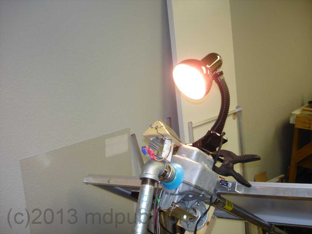
The sensor head idea worked well indoors in my workshop. After tuning the pots on the controller, the tracker would follow a lamp quite well,
always staying pointed toward it, no matter how I moved it around. I was very pleased. I wanted to take the unit outside for some testing under
the actual sun, but there wasn't time to disassemble it, move it outside, reassemble it, test it, then disassemble it again. I had simply run
out of time. So I hoped for the best, packed it up, and trucked it to Arizona.
Once outdoor testing in Arizona began though, a problem was discovered. The much stronger natural sunlight seemed to be saturating the output of the solar
cells even if they were at quite oblique angles to the sun. This resulted in the tracker not following the sun with any real accuracy. No amount of
adjusting the pots on the controller would make it track the sun accurately.
A solution to the problem was found by mounting an occulting bar in front of the solar cells, and applying black tape to cover part of the solar cells.
As the sun moves west the bar shades the east cell more and the west cell less, resulting in the necessary voltage difference needed to make the tracker
move and follow the sun accurately.
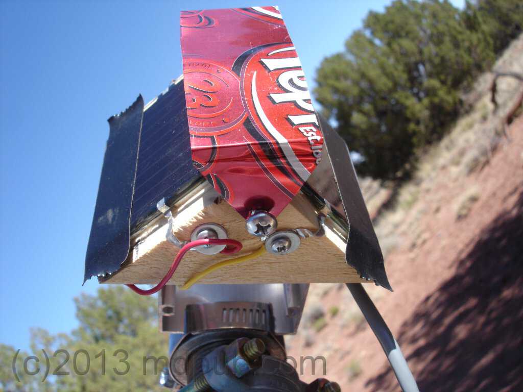
This first occulting bar was a quick and dirty proof of concept piece cut out of an aluminum soft drink can, which happened to be the only thin sheet
metal I had on hand at the time.
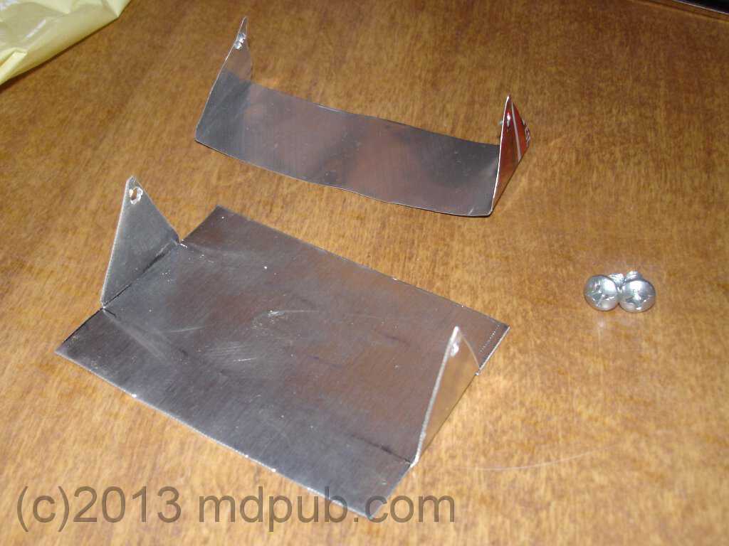
The first prototype occulting bar worked so well that a permanent occulting bar, made of 1/32 sheet aluminum, procured from the hardware
store in town, was fabricated the next day. This bar was made wider so so it would cast a wider shadow and I could do away with the tape
on the solar cells.
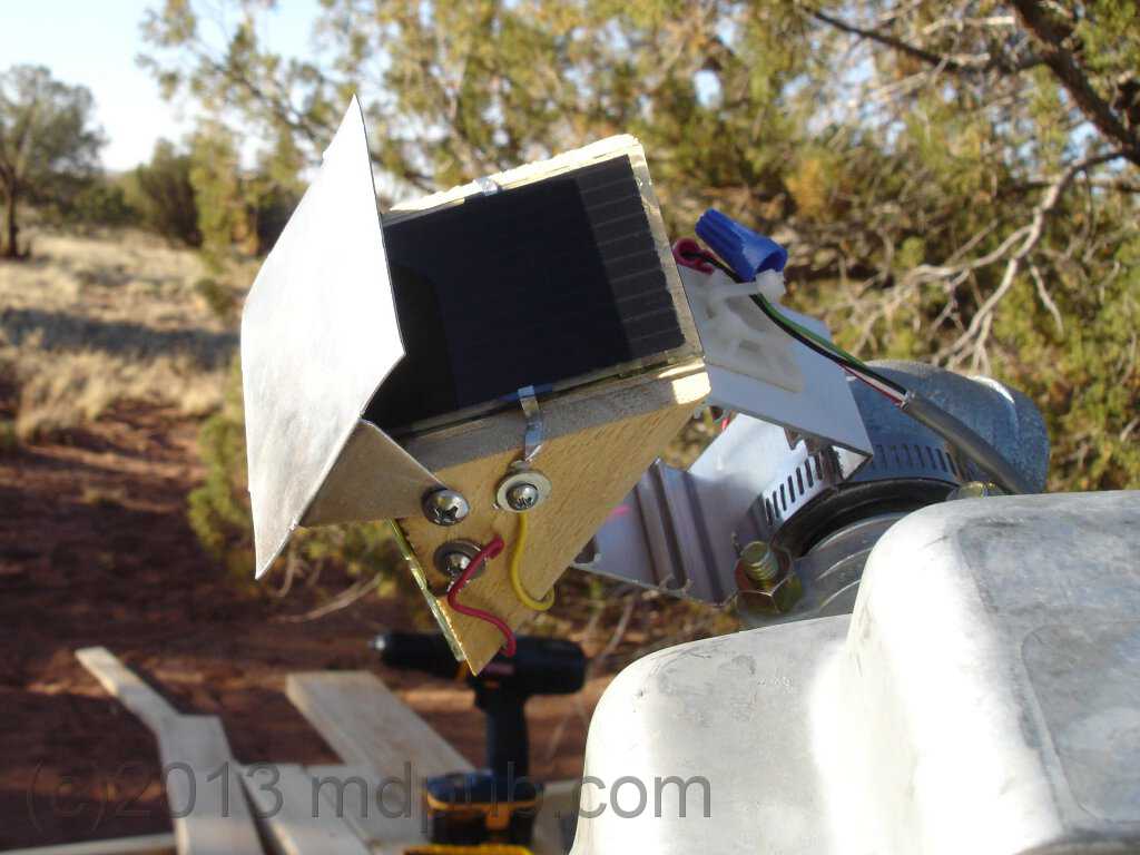
The occulting bar is mounted on two screws that allow it to pivot east and west. This allows for fine-tuning the pointing accuracy of the tracker.
with this bar in place, the tracker really began working well.
In the photo you can see how the occulting bar is shading most of the east cell. The sun doesn't have to move far before the difference in
output between the cells is enough to make the tracker move.
Here is a photo of the final version of the occulting bar with dimensions.
The occulting bar works great. Here it is late afternoon and the tracker is all the way over to its west limit after following the sun
all day. The unit is working very well. I couldn't be much more pleased with it.
Calibration of the tracker is pretty simple. On a clear day, with the sun well up, connect a laptop computer to the MBED module
in the tracker, then open a terminal program to see the numbers being put out by the MBED. Adjust the occulting bar so that it
is centered. Use the manual controls to position the tracker so that it is centered on the sun, then turn off the inverter so
the tracker can't move on its own. Adjust the trimpots until the east and west numbers are both approximately 0.5. Get them
as close as possible. Be fairly quick or the sun may move enough to throw off the calibration. You can always manually re-center the
tracker on the sun and try again. Once you are happy with the numbers, turn the inverter back on and see how well the tracker follows the sun.
The tracking can be tweaked by moving the occulting bar slightly east or west and the tracker will move in the opposite direction
Since the sun moves so slowly, calibration can take a while. You may have to wait an hour or two, or even most of a day after making an
adjustment to determine if the tracker is following the sun accurately, or if more tweaking is necessary.
Here the tracker is a little east of center late in the morning on a somewhat cloudy day. Even through thin clouds the tracker
works well. The tracker stops tracking when thick clouds roll in and the brightness of the sky tends to be fairly uniform. As soon
as they thin out though, the tracker latches back on the sun.
This shows my temporary testing setup in Arizona. There is a large, deep-cycle battery in the battery box. On top of the bin is my
home-made charge controller and a power inverter to supply 120V AC to the cabin via the orange extension cord. Eventually I will
weatherproof and permanently install the tracker. The batteries and electronics will live in a weatherproof enclosure nearby, and
underground wiring for 120V AC and 12V DC will go to the cabin, and a remote power switch for the inverter, and battery voltage
meter will be mounted in the cabin. That's the plan anyway.
It gets really windy on my Arizona property. On any given day we can see gusts of 35 mph or even more in the afternoons. Something about the location, between
the mountains in the south and the desert in the north, drives a daily strong wind out of the south. It gets even worse if there is a storm. The
winds could easily blow over the solar tracker. So I take the precaution of staking it down. This photo shows wooden stakes at the four corners of
the tracker base to keep it in place. Once I decide where to permanently place the tracker, I will probably use steel stakes to hold it in place
because they won't rot.
Here is a video showing the solar tracker in operation on my remote, off-grid, Arizona property.
UPDATE - I think I have found a cheap and easy way to weatherproof the sensor head. I sliced a 2 liter bottle in half and slipped it over
the sensor head. I had to cut a few slits in the bottom part of the bottle to make it slide around the square tubing at the base of the head.
Some clear tape holds it together. I can adjust the position of the occulting bar (if necessary) through the cap hole with a notched stick.
It will be interesting to see how well it stands up to the weather.
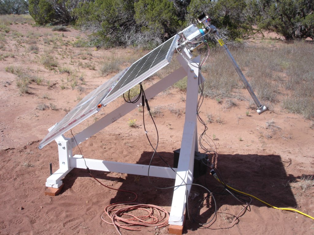
UPDATE - I have made some changes to the solar tracker. Firstly, as you can see in this photo, it has been painted to help protect the wood structure from the
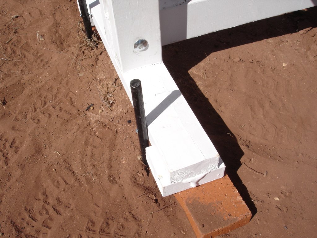
weather. It is also now sitting on top of bricks to keep it up off the ground at least a little bit and prevent the wood from absorbing moisture.
Click the photo for a larger view.
The original wooden stakes used to hold the tracker down in high winds have been replaced with long steel stakes driven deep into the ground. Long screws
go through holes in the stakes and into the wood to securely anchor the tracker. A storm front came through with hurricane force winds shortly after I
made this modification. The tracker handled it with no problem.
Click the photo for a larger view.
A horizontal support bar has been added to help stabilize the panels and prevent them from flapping around in strong winds. Wire ties are threaded
through holes in the edges of the panel frames and loop around the bar. The wire ties had not yet been installed when I took this picture.
Click the photo for a larger view.
The horizontal support bar was attached by welding a 1/2 inch steel pipe coupling to the main 1 inch support pipe. Two 24 inch long pieces of 1/2 inch
pipe then thread into it to make the horizontal support bar.
Click the photo for a larger view.
UPDATE - The old limit switches have been replaced with new sealed units to keep out dust and moisture.
Click the photo for a larger view.
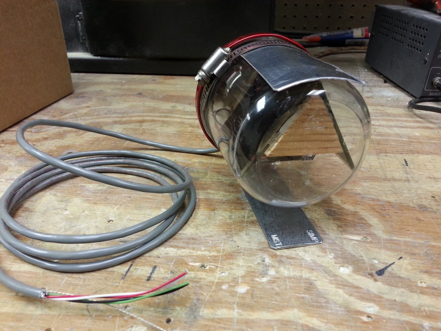
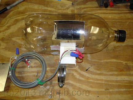
UPDATE - I have built a new, weatherproof sensor head for the system. It is still based on two small, thin-film, Copper Indium di Selenide (CIS) solar cells set at an angle to each
other, but now it is mounted inside a clear plastic container. The container originally held a Bluetooth speaker I bought for use with my phone. I immediately saw a potential new use
for the container. I had also considered using peanut butter jars and Mason jars, but this particular container was just perfect.
Click the photo for a larger view.
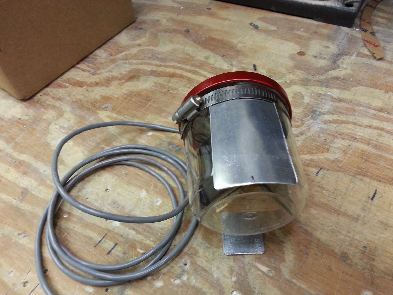
The occulting bar is now located on the outside of the container for ease of fine tuning the tracking. It is held in place with a simple hose clamp. Once the new sensor head
is mounted on the tracking system, a bead of silicone caulk will be applied around the lip of the jar lid to seal it against moisture.
Click the photo for a larger view.
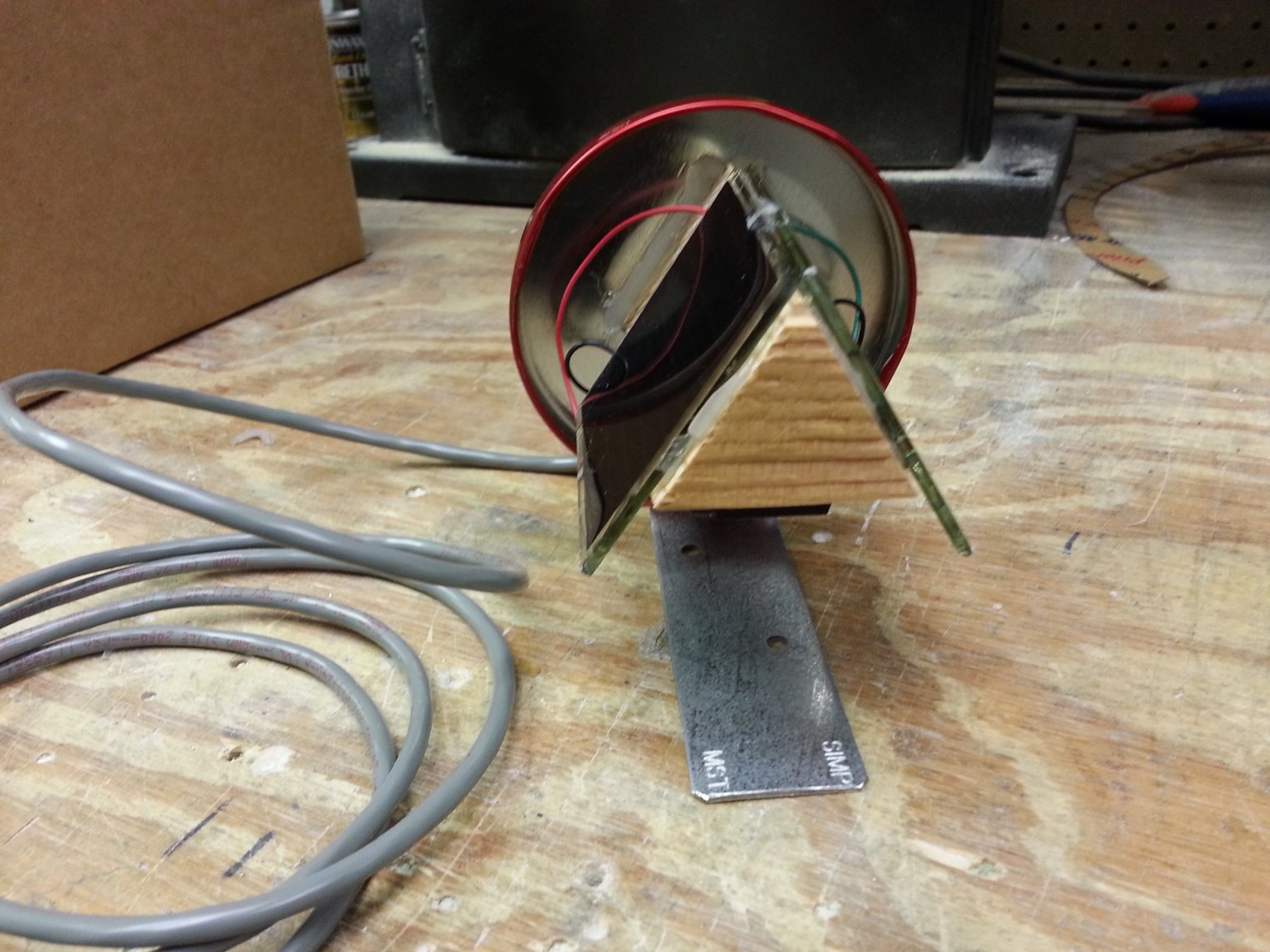
Here is a view of the sensor head with the jar removed. The original head had the two CIS solar cells mounted at 90 degrees to each other. Such an arrangement would not fit
in this jar, so I mounted the cells at a more acute 60 degree angle.
Click the photo for a larger view.
This photo shows the underside of the sensor head where a terminal block was attached so that wires could be terminated neatly. It also shows how the mounting foot is screwed
onto the jar lid. The mounting foot will be clamped to the main shaft of the tracker with a hose clamp.
Click the photo for a larger view.
UPDATE - The new sensor head has been installed and is working! I don't have to worry about wind, rain, dew and dust damaging the sensor head anymore. That is a major
relief. The new head does seem to result in the tracker hunting around a little more for the ideal position than the last one did, especially on partly cloudy days. I think
it is a result of turning the solar cells by 90 degrees in this unit as opposed to the first one. Since these cells are made of an array of tiny cells, and not just one big
cell, this different orientation results in a larger change in output Voltage with a small change in shading. I made the change intentionally because the last unit seemed
rather insensitive to orientation unless there was a huge amount of shading of the cells. It doesn't seem like it is doing a really excessive amount of hunting to me, but I may
tweak the software a bit to reduce it anyway. Just maybe slightly increasing the required voltage difference between the cells before the system moves may reduce the hunting while
still maintaining adequate pointing accuracy.
Click the photo for a larger view.
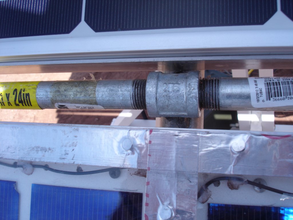
UPDATE - I was having some trouble with the pipe connections on the solar tracker coming loose. The motor would turn, but nothing would move because the pipes were unscrewing at the union.
Also the 90 degree fitting for the counterweight would sometimes loosen and the counterweight would flop down uselessly. So I drilled some through holes at the problematic joints and stuck
nails through them to keep the joints from coming loose. I would have used Cotter Pins, but didn't feel like driving nearly 50 miles round-trip to the nearest hardware store to buy some. I
had plenty of nails on hand, and they worked fine to lock up the two joints that were giving me problems.
 The first step was to come up with a way mount the drive motor and solar panel(s). I did a little back of the envelope brainstorming and
designed a mount for the tracking system that was simple, inexpensive, and easily broken down for transport. It is made mostly from 2X4s
and standard pipe fittings, and is held together with carriage bolts.
The first step was to come up with a way mount the drive motor and solar panel(s). I did a little back of the envelope brainstorming and
designed a mount for the tracking system that was simple, inexpensive, and easily broken down for transport. It is made mostly from 2X4s
and standard pipe fittings, and is held together with carriage bolts.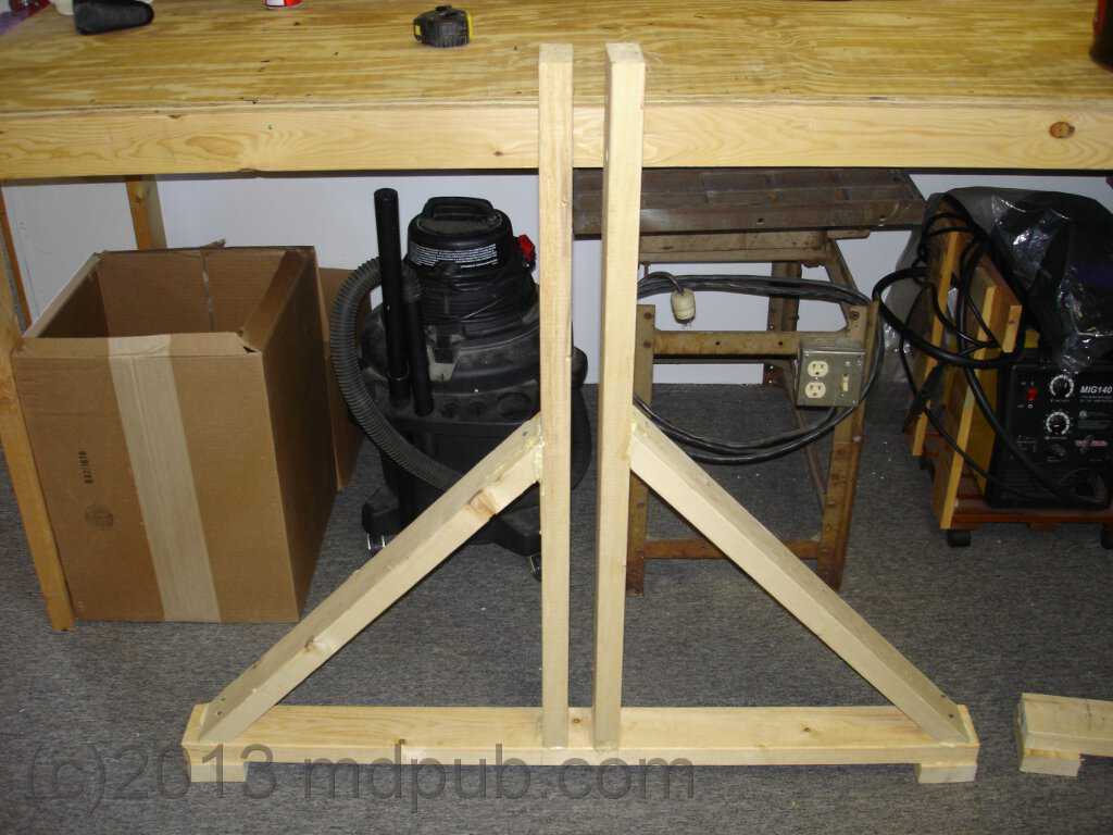

 This photo shows two aluminum frames for holding panels clamped onto the drive pipe. By turning the panels 90 degrees, two will now fit. The frames
are slightly different sizes because the panels they will be holding are slightly different.
This photo shows two aluminum frames for holding panels clamped onto the drive pipe. By turning the panels 90 degrees, two will now fit. The frames
are slightly different sizes because the panels they will be holding are slightly different.
 This photo shows the two solar panels in place. The panels just drop right into the frames, which have been made slightly larger than the outside
dimensions of the panels. Screws hold the panels in place so the wind can't blow them out of the frames.
This photo shows the two solar panels in place. The panels just drop right into the frames, which have been made slightly larger than the outside
dimensions of the panels. Screws hold the panels in place so the wind can't blow them out of the frames.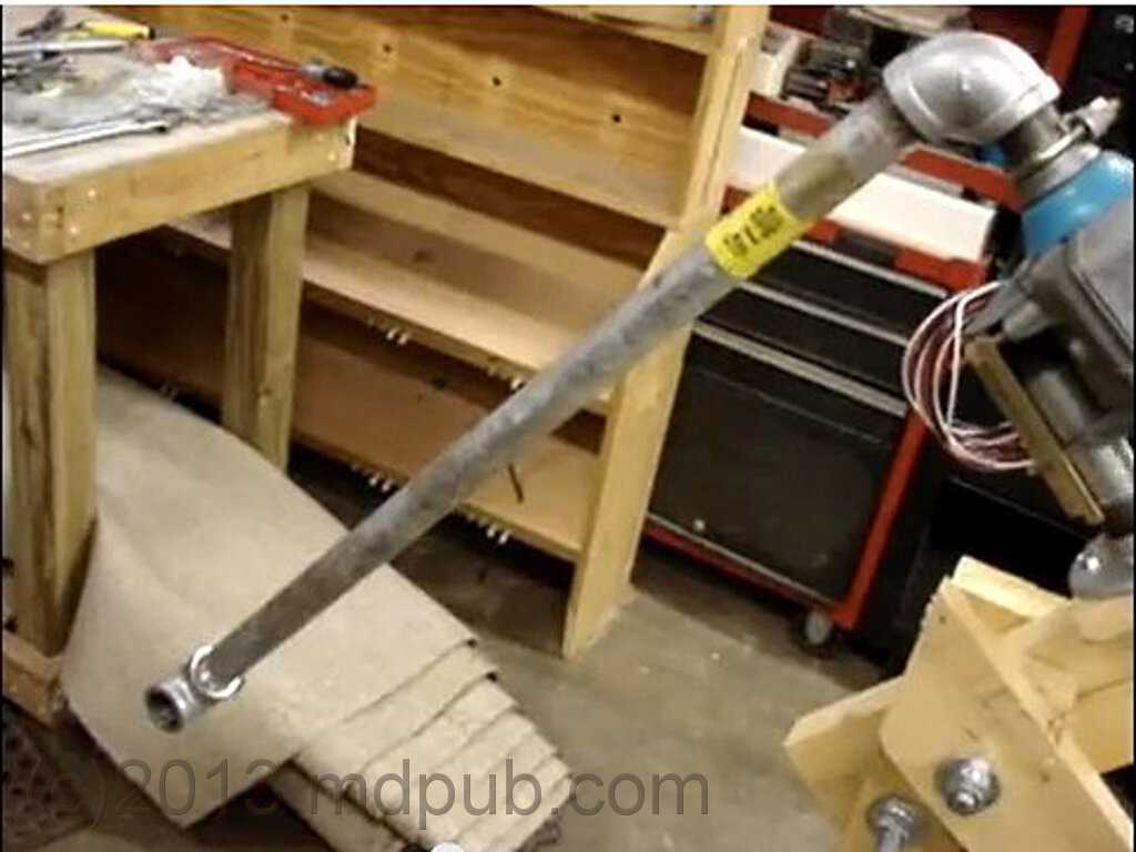

 UPDATE - I think I have found a cheap and easy way to weatherproof the sensor head. I sliced a 2 liter bottle in half and slipped it over
the sensor head. I had to cut a few slits in the bottom part of the bottle to make it slide around the square tubing at the base of the head.
Some clear tape holds it together. I can adjust the position of the occulting bar (if necessary) through the cap hole with a notched stick.
It will be interesting to see how well it stands up to the weather.
UPDATE - I think I have found a cheap and easy way to weatherproof the sensor head. I sliced a 2 liter bottle in half and slipped it over
the sensor head. I had to cut a few slits in the bottom part of the bottle to make it slide around the square tubing at the base of the head.
Some clear tape holds it together. I can adjust the position of the occulting bar (if necessary) through the cap hole with a notched stick.
It will be interesting to see how well it stands up to the weather.