My Home-Made Biomass Gasifier
Making your own gasifier is easy
I've built a lot of alternative energy projects over the years. See my home-built solar panel and
wind turbine pages. I've always wanted to build
a wood or biomass gasifier too. Why? Well, the internal combustion engine is really an important part of our society and the basis of a lot of
our transportation and portable power technology. It isn't going to be going away any time soon. I've mastered making my own electricity from the
sun and wind, but that doesn't help my truck go down the road, power the lawn mower, or run my generator on cloudy, windless days. Those all have
internal combustion engines, and they all need fuel to run. I finally decided it was time to master making my own fuel. Why pay the Arabs for it
if I can make a working substitute myself?
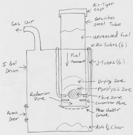
So what is A biomass gasifier? Basically is a chemical reactor that converts wood, or other biomass substances, into a combustible gas that can
be burned for heating, cooking, or for running an internal combustion engine. This is achieved by partially combusting the biomass in the reactor, and
using the heat generated to pyrolyse or thermally break down the rest of the material into volatile gasses.
A well built reactor will also convert
combustion byproducts like CO2 and water vapor into flammable CO and H2 by passing them over a bed of hot charcoal where they will get reduced.
Thus the gasifier converts most of the mass of the wood (or other biomass feedstock) into flammable gasses with only some ash and unburned charcoal
residue. That is the theory anyway. This is an extreme over-simplification of how the gasifier really works. Wood and other biomass is made of
incredibly complex macro-molecules like Cellulose and Lignin that break down into hundreds or thousands of different smaller molecules as the
reaction proceeds. There are thousands of different complex chemical reactions going on inside the reactor. The overall result though, if the gasifier
is working well, is represented in the simple formulas above.
Ideally, the gasifier would break down biomass into nothing but Methane (and other simple gaseous hydrocarbons), Hydrogen and Carbon Monoxide. Here in the real
world though, things rarely work ideally. The dirty (literally) little secret about biomass gasification is tar production. Above I said that the
macro-molecules that make up biomass get broken down into smaller molecules. Some of those smaller molecules are still pretty big though. If the gasifier
is working well, these big breakdown by-products will be further "cracked" into smaller molecules. If the gasifier isn't working so well, these big
molecules will wind up in the gas being produced. They will condense out of the gas as a thick, sticky, black, semi-liquid that very closely resembles
roofing or road tar, but is even stinkier. Even a well-built gasifier produces a small amount of tar. Most real-world applications can't handle much, or even any,
tar. This story of my struggle to design and build a working biomass gasifier could actually be accurately described as a battle to reduce tar production.
So below is the most important of all chemical reactions a novice gasifier builder needs to know.
Biomass + Poorly Designed Gasifier = Tar!
A word of warning here. This project is dangerous. Metal working and welding are involved in the construction, so all the usual dangers of laceration,
burns and electrocution that go along with them are present. Use all necessary precautions. Also, the operation of a biomass gasifier produces lots
of heat, flammable and poisonous gasses. Never operate the gasifier indoors. The gasses produced are flammable and potentially explosive if allowed
to accumulate in an enclosed space, like a building. Also, the Carbon Monoxide the gasifier produces is lethal! Only operate the
gasifier outdoors and try to stay up wind of the unit when it is running. Treat the gas coming out of the gasifier with the same respect as you
would for the natural gas that you may have piped into your house. It is just as potentially explosive and deadly.
My original goals with this gasifier project, were to build a compact and simple gasifier, that used inexpensive feedstock (like wood chips or mulch that is
available very inexpensively, or even free), and produced high-quality gas.
Little did I know in the beginning that these goals appear to be largely incompatible. Simple gasifiers don't produce good gas, and inexpensive
fuel is the most difficult to work with.
Only after working away at the project for a while, and going through several major redesigns of the gasifier and changes of fuels, did I achieve
a system that works reasonably well. So this web site will chronicle the evolution of the gasifier, from early failure, to ultimate success. I will
point out the mistakes I made and blind alleys I went down, so that you won't have to make those same mistakes.
As I said above, my original goals were to produce high quality gas from a compact, simple and easy to fabricate design. My research showed that the downdraft gasifier
design generally produced the best quality gas. However, there are a bewildering number of variations on the downdraft design. Some quite complex
and difficult to fabricate, others much simpler. So naturally I gravitated toward the simpler designs. I originally aimed for a simple open core
design, like the one on the far left of the bottom row of the diagram.
I found out through experience that the simple designs just don't seem to work very well. At least I couldn't get them to work very well. The reason
there are so many complicated designs is that they work so much better. So I started out building a simple open core design. But by the time I had a
reasonably well working gasifier, the design had morphed into something that looks a lot more like the complex J-Tube design on the far right of the
middle row. Fortunately I was able to incrementally modify the original design to get to the final design, and didn't have to completely start over again.
I chose the open core stratified downdraft gasifier design because it was by far the simplest of all the designs I could find. Everything I read about
it (at the time) said it should work great. I saw vague references to people in India having great success with this design. So I thought I couldn't fail.
Turns out this design sucks. It is really good at producing tar, but not so great at making high quality gas. Unfortunately I had to build it before I
figured it out.
So here is my original design for a stratified downdraft gasifier. It didn't work very well, but it provided a good base to build on. I have lots of photos
from this phase of the construction, and most of what is shown below wound up in the final design.
I did make a few really good decisions at this point. I decided I wanted to make the flame tube easily removable, since I figured some tinkering would be necessary.
This made later modifications much easier. I also decided to make a big access door in the side of the drum for cleaning out ashes. The door also came in handy
to give me access for making modifications.
The one big unknown at this point was what I was going to use for a grate and how I was going to make it shake. So that part of the plan is a little vague. I
just forged ahead with the construction and decided to solve that problem later.
As I said above, I made a lot of early mistakes with this project. I was fortunate though in starting with an good foundation that I was able to
modify and build on to ultimately make a working gasifier. In building another unit, even knowing what I know now, I would start out exactly the same way.
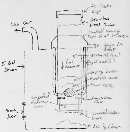
The basic structure of the gasifier is built around a 5 gallon steel drum, and a stainless steel tube 4 1/4 inches in inside diameter, and 14 inches long.
These dimensions are not really critical. The tube could be a little longer or shorter, and a little wider or narrower in diameter. I got the drum at work.
We use a variety of chemicals that come in small metal drums like these, and always have a lot of empties around. The stainless steel tube came from a
scrap yard. It was a little pricey. I have since discovered that many fire extinguishers have stainless steel bodies that are about the right size for use in
a gasifier. Old fire extinguishers are easy to find and cheap.
The purpose of the drum is to be the main body of the gasifier unit. It contains everything and collects all the gas, ash and char the unit will produce. The
smaller of the two bungs on the drum will be the gas outlet. The
stainless steel tube serves several purposes. The bottom of the tube will be the reactor where the gasification takes place. The remainder of the tube is a
hopper for holding un reacted fuel. The tube will be subjected to very high temperatures and corrosive gasses. Stainless steel is the obvious choice here.
I started by cutting a large hole in the top of the drum so the stainless steel flame tube can be inserted. The hole was made very oversize, a fortuitous decision
as it turned out. The hole is offset to the side of the drum opposite the small bung. The large bung was sacrificed, since I wasn't planning on using it.
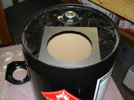
Next I cut a flange from a piece of 1/8 in steel for mounting the flame tube into the drum.
I installed clip nuts on the corners of the hole in the top of the drum, and drilled mating holes in the above flange. This would allow me to bolt the flange
down to the top of the drum. My idea here was to make the core of the gasifier easily removable for service and modification.
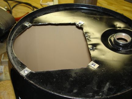
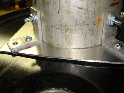
Next, I made some angle brackets out of aluminum and bolted the flame tube to the flange. I left 6 1/2 inches of the flame tube sticking up above the
flange. The rest protrudes down into the drum. At this point in the project I did not yet have access to a welder.
Even if I had one, I'm not sure I could have welded the mild steel flange to the stainless steel flame tube anyway. Here the unit is being test fit on top of
the drum. The holes in the ends of the angle brackets are over the clip nuts in the top of the drum.
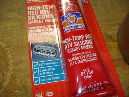
This is my new best friend. I went through several tubes of this high temperature silicone gasket material. I used it to seal every crack, crevasse, joint,
seam and bolt hole in the gasifier. It works great.
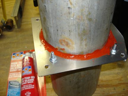
Here I have used the gasket material to seal the gap between the flange and the flame tube.
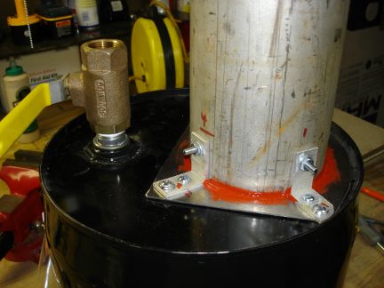
Another test fit to make sure all the bolt holes line up with the clip nuts in the top of the drum. I have also installed a ball valve on the small bung.
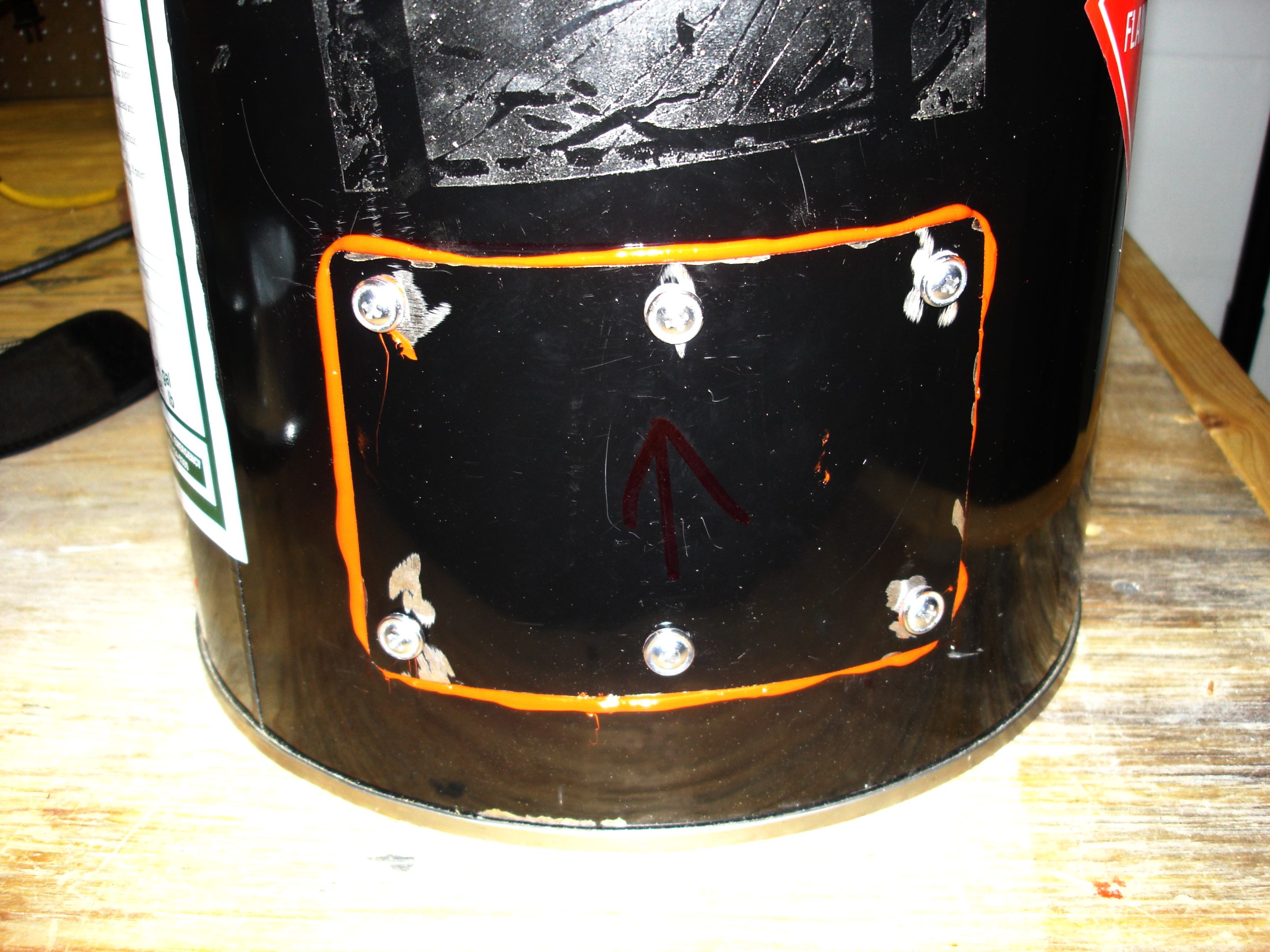
Here is the access door in the side of the drum. I cut a rectangular hole in the side of the drum just big enough for me to get my hands inside to clean
out the ash and char. then I cut a larger rectangular piece out of another drum to serve as the door. The door is held in place with six more clip nuts
and bolts and sealed with lots of silicone gasket material.
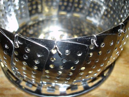
It was time to tackle the problem of what to do for a grate at the bottom of the flame tube. At a total loss for ideas, I spotted a stainless steel
vegetable steamer at a yard sale. Inspiration struck. I decided to try using the steamer as a grate. I wired the petals together with stainless steel
wire to keep the steamer in this bowl shape.
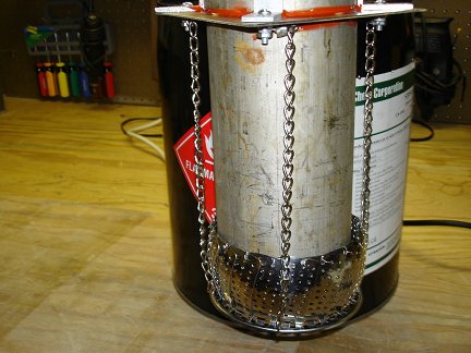
Here the steamer is suspended on chains a little bit below the bottom of the flame tube. The steamer has been formed into a bowl shape a little larger
than the diameter of the flame tube. I suspended the steamer from the bottom of the flange with chains so that it could move back and forth a little.
I next tied a length of stainless steel wire (not shown) to the steamer and ran the wire outside the drum through a tiny hole drilled in the drum.
Tugging on the wire made the steamer shake and twist. I wasn't thrilled with the result, but I figured it would work well enough for a test run or two
of the gasifier.
Eventually I came up with a much better grate design. It appears further down the page.
This photo shows how the other ends of the chains are attached to the bolts on the bottom of the flange. I used ring terminals crimped onto the
ends of the chains.
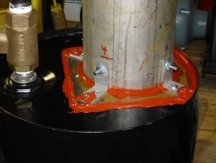
With the internal parts all sorted out, it was time to button up the gasifier. Here I have mounted to central core assembly (flame tube, flange and grate)
and used liberal amounts of the high-temp silicone gasket material to seal up the unit. I could hardly wait for the silicone to cure so I could start the
test runs.
Here is the air blower I used to pull air through the gasifier. This blower last saw use in
my home-built jet engine project. Most gasifier projects I have seen use a blower to pull air
through the unit. It is usually used to start the gasifier, then once running, the vacuum from the intake of the engine the gasifier is meant to power
keeps the gas flowing. This blower is a little under powered. However, it is the only all metal blower I could find. Most blowers these days are full
of plastic parts. The plastic would melt at the temperatures the gasifier operates at. So I made do with my undersized blower. I actually had some
success with it, after I modified the design of the gasifier.
I used a flexible metal natural gas line like the ones used on gas ranges and dryers to connect the gasifier to the blower. The gas line is a little undersized, and
probably contributed to the poor performance of the pump.
My dream fuel for the gasifier is free wood chips and mulch available from lots of places nearby. I know of at least three places I pass on a regular
basis that have signs offering free mulch to anyone who would come and haul it away. There are probably dozens of other sources I could find with a
little research. So I got myself a bag of wood chips. The chips were very wet. So here I am drying them with a fan. After 2 weeks under the fan, they
were bone dry and ready to burn in the gasifier. I realized that if this worked, I'd have to find a less energy intensive way of drying the wood chips
in the future.
Now it was time to give some thought to how to start up the gasifier. A lot of people build in a port in the side of their gasifier so they can stick a
blowtorch inside and start the fire. I decided to take a different approach. I decided to pre-load the reduction section of the gasifier with hot charcoal, and
then I'd fill the hopper up the rest of the way with whatever fuel I was going to burn. This starting procedure actually works quite well, and I have continued
to use it, even through all the redesigns and fuel changes the gasifier has gone through. With the reduction section full of hot charcoal, the reaction
starts almost immediately, and the gasifier (in its final design below) is producing good gas in only a couple of minutes.
I use hard wood lump charcoal, not briquettes, though they might work too. I pulverize the charcoal down to pieces no larger than about 1/4 - 1/3 of
an inch across.
Here I am lighting the charcoal with my propane torch. The pulverized charcoal is in yet another stainless steel vegetable steamer. These things
are just so amazingly useful for so many non-vegetable steaming tasks. The small pieces of hardwood charcoal light easily and burn very hot. Only a
few quick passes from the torch gets them going. Once
the charcoal is good and hot, I dump it into the flame tube of the gasifier, and fill it up to the top of the reduction section. Then I fill the
flame tube up the rest of the way with fuel.
Here is a photo of the completed Mark I gasifier in operation. Ignore the hopper extension at the top of the flame tube. It was an experiment I tried
to increase the fuel capacity of the gasifier. I no longer use it. The aluminum foil is on top of it because it was raining a little bit, and I was
trying to keep the fuel dry.
I could never get the gasifier to work well. It would produce some flammable gas sometimes, but mainly it just produced a lot of stinky tar and smoke.
I was having a lot of trouble with zone migration. That is where the flame zone (and hence all the other zones too) moves up the fuel column, instead
of the fuel moving down. The result was that in short order, the flame would reach the top of the fuel hopper section and there would be no more fuel
for the gasifier to gasify. The fuel got converted mostly to charcoal, with lots of tar and a little gas as byproducts. If I wanted a machine to make
charcoal and tar, this would be a great design. However, as a machine to make gas, it was a flop.
After doing some more research, (research I probably should have done up front), I came to realize that wood chips are a difficult fuel. The non uniform size
and shape of the chips makes them difficult to burn in a simple gasifier. So I switched fuels. I wanted to use wood pellets, but they are hard to find here
in Florida. So I settled on hay pellets. I could get them from feed stores, and they were reasonably priced. They seemed like a reasonable substitute for
wood pellets.
The result with the hay pellets was only marginally better than with the wood chips. More gas was produced, but the zone migration problem didn't go away,
and the tar problem was just as bad, and if anything, even stinkier. The gasifier didn't seem to be getting anywhere near as hot as it ought to be. I knew
that low temperature operation would lead to less gas and increased tar. I suspected that poor air flow through the fuel was part of the problem. The uniform
size, shape and composition of the pellets made them an ideal fuel, as far as I could tell. So I had to face the fact that the problem was the design of
the gasifier, not the fuel. The final nail in the coffin of this design was when I found the blog of another gasifier tinkerer who was complaining about
the open core design. He was lamenting that he had built a tar producing machine instead of a gasifier. It was time for a major re-think.
So I sat down and made a list of the problems I was having with the gasifier, in order of their severity. My day job involves use of a lot of statistical analysis.
One tool we use a lot at work is Pareto Charting. With a Pareto Chart, you list the problems or defects in your process in order from highest to lowest percentage.
Then you start trying to fix the problems at the top of the list because fixing them first will produce the biggest improvement in your product. I had a
list of defects with the gasifier, and so I listed them in what seemed like the most logical order.
Zone Migration
Poor Air Flow
Low Temperature Operation
Excessive Tar Production
Shaker Grate Not Working Well
Weak Air Pump
Looking at the list, it was obvious to me that the zone migration problem was the biggest problem I was facing. The fuel was being mostly converted into
charcoal, rather than being properly gasified. Solving that problem would make a big improvement in the operation of the gasifier. I also realized looking
at the list that solving the poor air flow problem would also probably improve or even eliminate other problems on the list like low temperature and tar
production. So I decided to tackle the top two problems first, and tackle the others as opportunities presented themselves.
So it was back to the drawing board. I knew that the easiest way to solve the zone migration problem was to cap the top of the flame tube. The flame was
simply moving up-wind toward the source of oxygen. Since the original design required air to move through the whole fuel column, the flame simply went
up the column toward the source of air and created the zone migration problem. Capping the tube meant I had to find a new way to get the air into the
gasifier.
I studied the various gasifier designs. It was clear to me I needed to install air inlet tubes near the bottom of the flame tube. It looked like the
easiest way to do it, and still allow the core section to be removable was to install J-Tubes. The J-Tubes would also have the added benefit
of pre-heating the air, since they would pass through the hot gas in the drum before entering the flame tube. I also noticed (maybe a little late)
that almost all gasifier designs have a constriction or throat where the unit narrows below the flame zone. Further research explained that the constriction
helped reduce tar production by forcing the volatiles produced in the pyrolysis zone to pass near or through the hot flame zone where the tars get cracked
into gas. I decided that while I had the gasifier apart I'd add a constrictor plate. Also, even though it wasn't a super high priority on my Pareto Chart,
I'd replace the shaker grate, since I saw a way to make a new one easily.
So goodbye simple open core design, and hello complex J-Tube design. Even though this was a major re-design, I could build on the already existing hardware.
I wouldn't have to start all over again from ground zero. This allowed the changes to happen fairly easily and quickly.
Here I have installed the six j-tubes. They are made of 3/8 inch copper tubing. They are called j-tubes because they are shaped like the letter J.
I used a large hose clamp cinched down tight to hold the tubes in place. The opening in the top of the drum needed to have a few notches cut in it
to accommodate a couple of the j-tubes that stuck out too far.
This photo also shows the chains that suspended the original vegetable steamer shaker grate. They will be reused with a new and improved grate below.
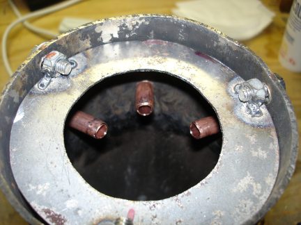
Here is a look up the bottom of the flame tube at the business ends of the j-tubes. Copper is probably not the ideal material to use here, since at least in
theory, the temperature at the point the air is injected could be high enough to melt them. So far my gasifier doesn't seem to get anywhere near that hot,
and the copper is holding up well. However, in my next gasifier, I will probably make at least the tips of the air inlets out of steel. Copper is just
so darn easy to bend and work with compared to steel tubing.
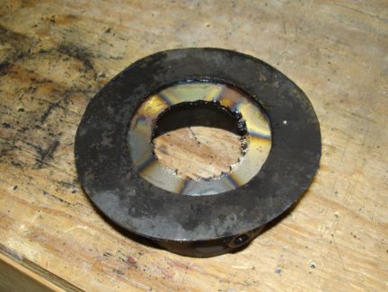
Here is a view of the constrictor plate I made. By this point in the project I had my own welder (Yahoo!) and was getting proficient at using it. To make
the plate I cut a circle out of 1/8 inch sheet steel that would fit in the bottom of the flame tube. Then I cut a 2 1/2 inch diameter hole in the center
of the circle. To mount the constrictor in the flame tube, I welded three 1/4-20 nuts to the plate, and drilled passage holes in the flame tube for three
1/4-20 bolts.
Here is a view of the constrictor plate installed in the bottom of the flame tube.
Here I have installed the new shaker grate. I made it by cutting the bottom out of a stainless steel colander I bought cheap at a yard sale. The colander
already had a lot of holes in it, but I drilled quite a few more in it as well. It is suspended under the flame tube by the same four chains that held the
original steamer grate. I used the same system of attaching a length of stainless steel wire to one corner of the grate and running it outside the drum.
Tugging on the wire makes the grate shake and twist. It is not an ideal system, but it seems to work. I put a ring on the outside end of the wire to
make it easier to grip.
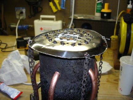
Here is a photo of the top of the re-assembled gasifier showing the tops of the j-tubes poking out of a sea of red silicone gasket material. It's a little
messy, but to me it was a thing of beauty.
Here is a look down the flame tube of the new and improved design.
Here is a video I shot down the flame tube of the re-assembled gasifier showing all the new parts and the shaker grate in operation.
Here is a video I shot of the new and improved gasifier in operation. At last, glimmers of hope. The unit is actually producing
decent amounts of flammable gas, and somewhat less tar. The gasifier is running a lot hotter than it had been too, but still not as hot as I expected.
After the run, looking under the cap
showed that the fuel was moving down the tube into the flame zone, as it was supposed to, and getting consumed. No more zone migration! I was very happy
about that. Still, the performance left a lot to be desired. There was still a lot of tar. Also, I was convinced the wimpy blower and losses in my skinny
outlet hose were really preventing the gasifier from reaching higher temperatures and impairing its performance.
After a few runs in this configuration, and burning through a lot of hay pellets, I became convinced that the next big problem that needed solving was
further improving the air flow through the unit. I had tried a few tests where I used a vacuum cleaner I had bought cheap at a yard sale in series with the
blower to increase the draw through the gasifier. I found that the temperature of the gasifier shot up with the increased air flow, and the quality of
the gas being produced seemed to increase. I quickly tarred up the vacuum cleaner, but I didn't care. I only paid a few bucks for it, and it served its
purpose in confirming my suspicion that I needed better air flow through the gasifier.
What to do? A more powerful blower was the obvious answer. Unfortunately, powerful, all metal blowers are very expensive. A new one was way out of my
price range for this project. I finally found a used one at a scrap yard and got it for almost nothing. But when I tried it out, I discovered the motor
was burned out. Not such a bargain after all. A new motor for it would cost over $100! Ouch. So scratch that idea.
Then it hit me. Why not blow compressed air through the gasifier, rather than use a blower to pull air through. My workshop has a huge air compressor.
I have essentially unlimited compressed air. I could adjust the pressure and flow rate through the gassifier easily with just a regulator and a valve.
Brilliant, if I do say so myself. Just one little problem. The current design had six air inlets. How would I join them together to connect them to
the compressed air supply?
Back to the drawing board again. While brainstorming on how to get compressed air into the gasifier, I noticed a steel air duct reduction fitting I had previously
used as an aborted attempt at a fuel hopper extension earlier in the project. I realized I could cut it down and make it a manifold that would cover the tops of all
six j-tubes. That would allow me to inject air into the system at only one point on the manifold and feed all six j-tubes. Brilliant, again, and this time it looked
foolproof. The manifold came together quickly.
I was sure that improving the air flow through the gasifier would make a big improvement in performance. However, comparing my design to other gasifiers
had me fretting about the small size of my reduction zone. It was pretty short compared to all other designs I had seen. I was worried that the quality
of the gas may be suffering due to an inadequate reduction zone. I decided that since I was once
again reworking the gasifier, I would lengthen the reduction zone. I figured it would be easy to do by simply welding a short length of steel tubing to
the bottom of the constrictor plate and lengthening the chains supporting the shaker grate. Unfortunately, I don't seem to have any photos of that
particular modification. I must have forgotten to take my camera to the workshop that day. I'll get a shot of the reduction zone extension the
next time I have the gasifier opened up. I believe I welded a 2 1/2 inch length of 3 1/2 ID inch steel tubing to the bottom of the constrictor plate,
then just lengthened the chains suspending the shaker grate.
My early decision to make the core of the gasifier removable once again allowed for these modifications to be made quickly and easily.
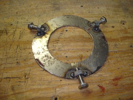
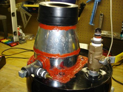
Here is the manifold I made to cover the inlets of all six j-tubes. It was cut from a 6 in to 4 in steel AC duct reduction fitting. It slips down over the
flame tube and gets siliconed to the top of the flange. A single air inlet fitting will be installed on the side of the manifold.
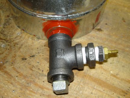
Here is the new single air inlet on the side of the manifold. I used a Tee fitting. One leg of the Tee goes into the manifold. One leg has a hose fitting
installed that I can use to inject compressed air. The third leg of the tee is plugged for now. My idea here was that I could start the gasifier on
compressed air, then once it was running, I could unscrew the plug, and let engine vacuum pull air through the gasifier (from whatever engine the gasifier
eventually gets connected to).
Here is the new and improved (again) gasifier, all buttoned up and sealed with yet more great gobs of red silicone gasket material, ready for a test
run. I couldn't wait to try it. So even though it was threatening rain, I set up the gasifier outside and fired it up.
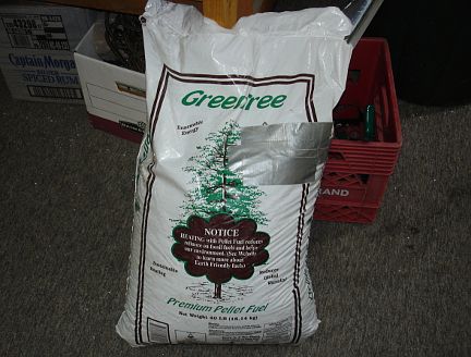
I finally found some wood pellets. On one of my trips to Arizona, I bought two 40 pound bags of wood pellets. They were dirt cheap too.
Less than $6 per bag. I couldn't find them to save my life in Florida. Every hardware and homecenter store in Arizona seems to carry them though.
Now I have plenty of high quality fuel for testing out the new and improved (again) gasifier. Fortunately I drive
out to Arizona twice a year. So getting 80 pounds of wood pellets back home in my big truck was not a problem.
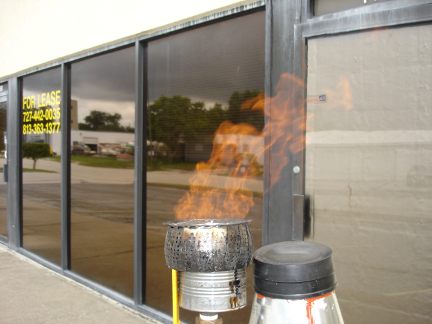
At last! The gasifier was working well. It is making lots of gas and hardly any tar. Everything was working great. The gasifier was
producing such a huge volume of gas, I decided I needed a better way of flaring it off. So I bodged together a
quick and dirty gas burner. I just drilled a bunch of holes in the bottom of
an 18 ounce steel can, and bolted it on top of the gas outlet pipe. I then but the old stainless steel vegetable steamer I originally
used as a shaker grate over the open top of the can. It works great as a burner. The flame doesn't blow out even in very strong wind
gusts. I'll need to increase the stack height since the heat from the burner is starting to cook the rubber and silicone parts a little.
Here is a video I shot during the first test run of the new and improved gasifier. A short while into the run,
I bodged together an improvised burner assembly to flare off the gas produced by the unit. It was windy and when I would
light the gas coming out of the outlet tube, the flame would get blown out every few seconds by a wind gust. The burner worked so well,
that I plan on making a lot less improvised version of it, and mounting higher up so the heat it produces is away from the rubber parts
on top of the gasifier.
You can see the dark black clouds reflected in the window behind the gasifier. A bad storm was rolling in. I had planned on running the
gasifier at a high flow rate, to see how long it took to burn through a full load of wood pellets. Somewhere less than an hour into the
run though, the skies opened up with a real gully washer of a rain storm that brought everything to a halt. I was drenched, then trapped
inside for over an hour waiting for the torrential rain to stop. At least the gasifier was nice and cool after that drenching when I
cleaned it out and put it away. I'll have to run that particular test another time.
Here is a video of another test run a week later. This time the weather was great, though very hot. I increased the
height of the stack under the burner. This time I managed to get in the timed run I wanted to do. It took about 50 minutes to use up
a full load of pellets in the gasifier.
I was just as pleased as could be with the performance of the gasifier. It was working great. The volume of gas it could produce was amazing.
As I cranked up the flow of compressed air to the unit, the flow of flammable gas to the burner increased until I had a real flame thrower
on my hands. The heat from the burner was so bad that it became difficult to approach the unit to make adjustments or shake the grate. I was
frankly amazed and thrilled at the volume of gas my little gasifier could produce. This small unit should be able to power even a huge engine.
I had succeeded far beyond my wildest dreams.
So now I had a working gasifier. Time to hook it up to an engine and start producing power, right? Well, not yet. The bright yellow color of the
burning gas tells me that there is still a lot of tar in the gas. There is not nearly as much as in the beginning, with the older design, when
tar would just run out of the pump and puddle around it, but there is still some tar in the gas, and tar is bad for engines. So I was determined
to reduce the amount of tar being produced. Further research led me to believe that reducing the size of the constriction in the hearth might
reduce the tar production. Most highly efficient gasifiers seem to have hearth constrictions that are on the order of about 1/3 the diameter
of the reactor. Mine was closer to 1/2 the diameter.
So I tore down the gasifier and welded in a new constrictor plate. Now the opening is only 1 1/2 inch in diameter. The theory here is that
by making the restriction smaller, the tar has to pass through the hottest part of the reaction zone and gets cracked. My original larger
opening was allowing tar to sneak out without passing through the hottest zone.
Here is a video of a night test of the modified gasifier with the smaller constriction. I am very happy
with this run. There is much less tar. The modification is working great. Running at night allowed me to see the true color of the
flame, and see that there is much less tar now.
While I had the gasifier set up and hot, I decided to do a test I had been wanting to do for a long time.
I ran the gasifier until the wood pellets were used up, then I loaded the hopper with charcoal. I ran the gasifier for a little
while on nothing but charcoal. The flame was very clean and almost pure blue (see the video). The gasifier produces very clean gas
on charcoal. There are two problems with running on charcoal though. First, charcoal burns a lot hotter than the wood pellets.
The gasifier wasn't designed to handle such high temperatures. Something would melt or break pretty quickly if I made a habit of
running on charcoal. I'd have to redesign and rebuild the gasifier to run on charcoal safely. Second, making charcoal throws away
a lot of the energy in the wood. I want to use that energy in my gasifier. So for now I will continue experimenting with burning
wood pellets and other biomass. It sure is nice to see what a clean, tar-free flame looks like though.
There is still some tar in the gas when burning wood pellets. I also see some ash
and the occasional spark come out of the burner. A look at the burner after a run shows some (not a lot) soot and coke-like material inside. All
this stuff will need to be filtered out before the gas gets piped into the intake of an engine, or the engine probably won't survive for long.
The valves would get gummed up and the cylinder walls would be scored. It would also be nice to cool the gas before sending it to the engine.
Cool gas is denser, and that means more gas could be pulled into the cylinder on each intake stroke. So I need to build a scrubber and cooler
for the gas.
A lot of other people use cyclone separators and radiators to clean and cool the gas from their gasifiers. I considered this option. However,
My metal working skills are somewhat limited. I also wanted to keep the unit as compact as possible. A cyclone and big radiators would make
the unit huge. I am hoping to make a unit that would eventually power a vehicle. Until I get all the bugs worked out, it will only power
stationary engines, but I don't want it to grow too big. I've seen trucks running on wood gasifiers. They are gigantic things sticking high up
out of the bed of the truck, or following behind on trailers. I'm hoping to make something more compact than that. Maybe something small
enough to fit in the trunk of a car with the trunk lid closed. That's my dream anyway. So I wanted to try to make a compact scrubber
cooler system to mate with my compact gasifier.
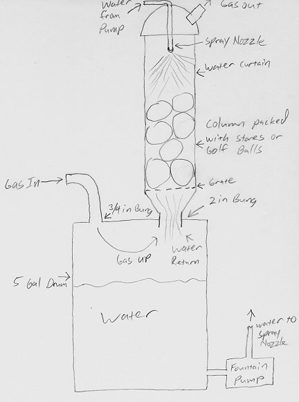
So here is my initial rough sketch of of a scrubber cooler system. My idea here is to use a water spray to clean up and cool the gas.
The gas would move up a column packed with either stones or golf balls, against the flow of water. The purpose of the packing material
is to increase the wet surface area the gas is exposed to as it passes up the scrubber column. The more surface area, the easier the gas
can give up its heat and suspended particles to the water.
Near the top of the column would be a spray nozzle that would spray out a cone of water, creating a
falling water curtain that the gas would have to pass up through. This would be the final cooling and scrubbing step. The water would then
flow down the column, through the packing material, and drain into the drum. Clean, cool gas would exit at the top of the column.
The whole thing would be built around another 5 gallon steel drum, just like the gasifier. The drum would hold a few gallons of water, and
collect all the residue scrubbed out of the gas. A fountain pump would be used to pump water up to the spray nozzle.
This is my initial idea anyway. Will it work? I don't know. At the very least, it will probably need some tweaking and reworking to get it
running right, just like the gasifier did. I have only just started building it, so it will be a while before I know if it works. I will post updates
here as the work progresses.
The results are in. And the answer is... It didn't work :-(
Well, I should say it didn't work very well. This is a photo of the completed scrubber unit. It removed some tar, as I could tell because the water
turned brown over time. However, there was still plenty of tar in the gas that passed through the scrubber. I was very disappointed. One bright
spot is the fact that the scrubber did a great job of cooling the gas, as I hoped it would. So I had cool, tarry gas, instead of hot, tarry gas.
So I did some more research. I found some information that I somehow missed earlier. It seems that this method of water spray scrubbing just
doesn't work very well when it comes to removing tar from gas. Well, I confirmed that.
I'm not going to spend a lot more time describing the water spray scrubber since it seems to be a dead end. Maybe it will come in handy for
cooling the gas, but I am going to have to come up with something else to take the tar out of the gas. Next I am going to look into ways of
further reducing the amount of tar produced by the gasifier, and more conventional methods of removing what remains from the gas.
In order to try to get some idea why my gasifier is still producing so much tar, I installed a thermocouple in it to measure the temperature at
the throat (constrictor plate). The temperature was higher than I expected. So the gasifier is getting hot enough to crack the tars. Something
else is wrong. Tar must be somehow be leaking out of the reaction tube without passing through the throat. I have some ideas where it could be
happening. I will be making some more modifications and trying another run when time permits.
Another test run of the gasifier. This time I had taken the gasifier completely apart and plugged every possible gap and joint where tar
could leak out of the reaction tube without having to pass through the hot zone and get cracked. The previous test run showed that the
gasifier is getting plenty hot enough to crack the tar. The only explanation I could see for the excess tar was leaks. Sure enough, I
saw where tar could sneak out around where the J-tubes entered the reaction tube, and around the outside of the constrictor plate. I
slathered on copious amounts of the red high-temp RTV silicone in all those places. This is not a permanent fix, since the heat will
quickly breakdown the silicone, but I figured I should be able tell if the early part of the run looked less tarry then usual. It does
seem less tarry. I need to find a way to permanently plug all those gaps. If not in this gasifier, then in my next one.
My future goals for the gasifier include of course getting it attached to and running an engine. Preferably an engine that would do something useful
like run a generator.
Other goals include automating the grate shaking so I don't have to do it myself every few minutes. I have some ideas on how to do that. At some point
I will probably redesign the whole shaker system to make it more robust and more amenable to automation. I am also
toying with the idea of an automatic pellet feeder, to keep the pellet hopper topped off. An automatic feeder would allow the unit to run for hours
at a stretch, rather than the 45 minutes or so I can get out of it on a single load of pellets. The limiting factor would then be the build-up of ash
and char in the bottom of the gasifier. That of course would lead to a new goal of an automated char removal system. Then there would be no real limit
on how long the unit could run.
This gasifier is a prototype unit. It is rather bodged together, and not terribly robust. Another goal I have is to eventually redesign the gasifier
to be more robust and rugged so that it could survive the rigors of years of hard use, and the banging around it would get being used to run a
vehicle. So I will probably be working on gasifier related projects for years to come.
 So I tore down the gasifier and welded in a new constrictor plate. Now the opening is only 1 1/2 inch in diameter. The theory here is that
by making the restriction smaller, the tar has to pass through the hottest part of the reaction zone and gets cracked. My original larger
opening was allowing tar to sneak out without passing through the hottest zone.
So I tore down the gasifier and welded in a new constrictor plate. Now the opening is only 1 1/2 inch in diameter. The theory here is that
by making the restriction smaller, the tar has to pass through the hottest part of the reaction zone and gets cracked. My original larger
opening was allowing tar to sneak out without passing through the hottest zone.
 I've built a lot of alternative energy projects over the years. See my home-built
 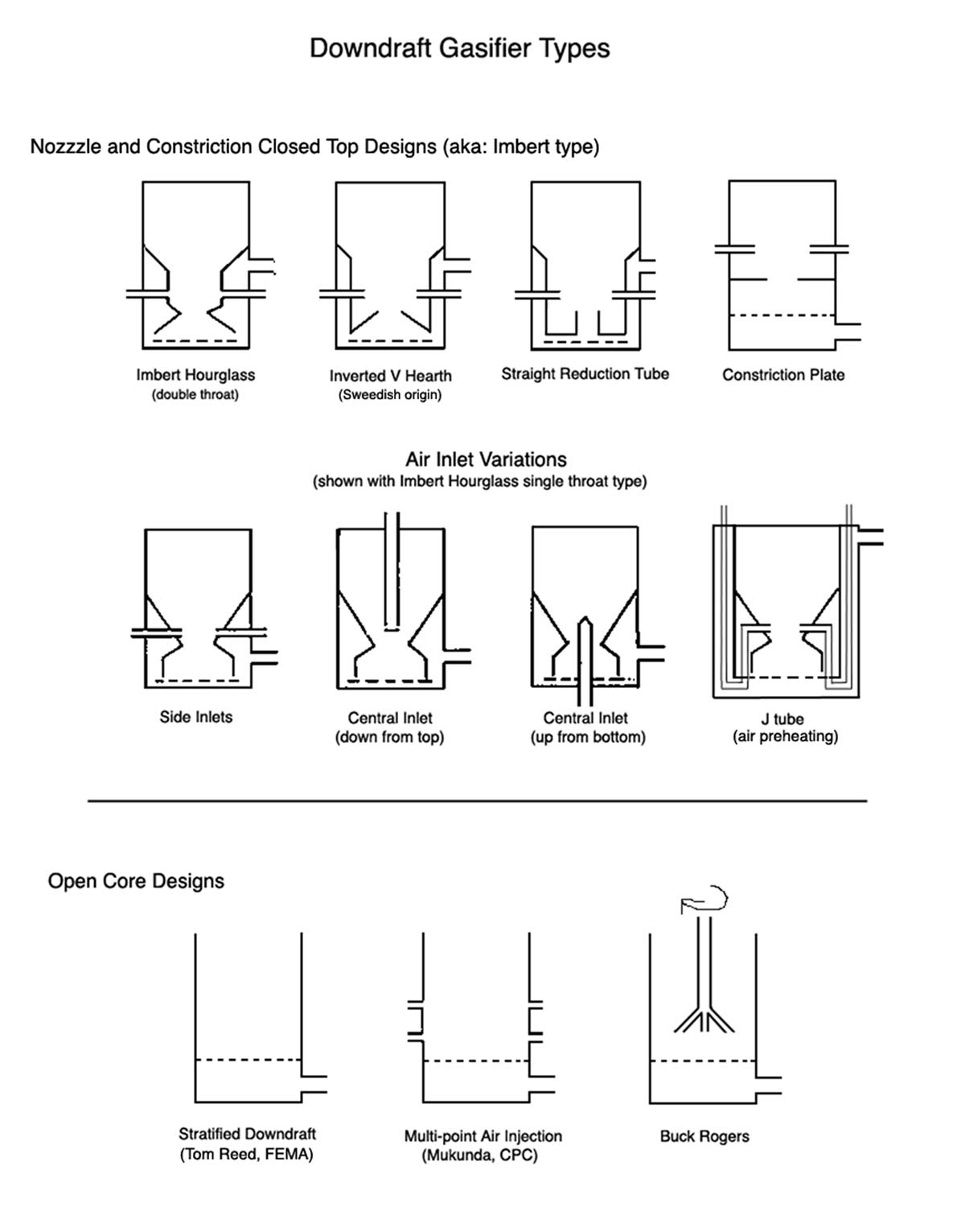 As I said above, my original goals were to produce high quality gas from a compact, simple and easy to fabricate design. My research showed that the downdraft gasifier
design generally produced the best quality gas. However, there are a bewildering number of variations on the downdraft design. Some quite complex
and difficult to fabricate, others much simpler. So naturally I gravitated toward the simpler designs. I originally aimed for a simple open core
design, like the one on the far left of the bottom row of the diagram.
As I said above, my original goals were to produce high quality gas from a compact, simple and easy to fabricate design. My research showed that the downdraft gasifier
design generally produced the best quality gas. However, there are a bewildering number of variations on the downdraft design. Some quite complex
and difficult to fabricate, others much simpler. So naturally I gravitated toward the simpler designs. I originally aimed for a simple open core
design, like the one on the far left of the bottom row of the diagram.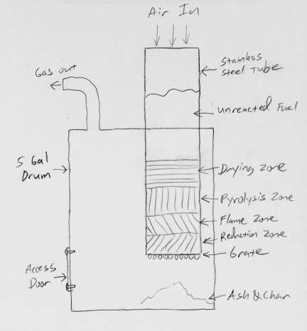 I chose the open core stratified downdraft gasifier design because it was by far the simplest of all the designs I could find. Everything I read about
it (at the time) said it should work great. I saw vague references to people in India having great success with this design. So I thought I couldn't fail.
Turns out this design sucks. It is really good at producing tar, but not so great at making high quality gas. Unfortunately I had to build it before I
figured it out.
I chose the open core stratified downdraft gasifier design because it was by far the simplest of all the designs I could find. Everything I read about
it (at the time) said it should work great. I saw vague references to people in India having great success with this design. So I thought I couldn't fail.
Turns out this design sucks. It is really good at producing tar, but not so great at making high quality gas. Unfortunately I had to build it before I
figured it out.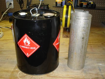 As I said above, I made a lot of early mistakes with this project. I was fortunate though in starting with an good foundation that I was able to
modify and build on to ultimately make a working gasifier. In building another unit, even knowing what I know now, I would start out exactly the same way.
As I said above, I made a lot of early mistakes with this project. I was fortunate though in starting with an good foundation that I was able to
modify and build on to ultimately make a working gasifier. In building another unit, even knowing what I know now, I would start out exactly the same way.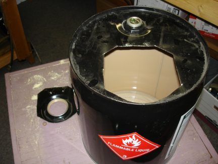 I started by cutting a large hole in the top of the drum so the stainless steel flame tube can be inserted. The hole was made very oversize, a fortuitous decision
as it turned out. The hole is offset to the side of the drum opposite the small bung. The large bung was sacrificed, since I wasn't planning on using it.
I started by cutting a large hole in the top of the drum so the stainless steel flame tube can be inserted. The hole was made very oversize, a fortuitous decision
as it turned out. The hole is offset to the side of the drum opposite the small bung. The large bung was sacrificed, since I wasn't planning on using it.
 Next I cut a flange from a piece of 1/8 in steel for mounting the flame tube into the drum.
 I installed clip nuts on the corners of the hole in the top of the drum, and drilled mating holes in the above flange. This would allow me to bolt the flange
down to the top of the drum. My idea here was to make the core of the gasifier easily removable for service and modification.
I installed clip nuts on the corners of the hole in the top of the drum, and drilled mating holes in the above flange. This would allow me to bolt the flange
down to the top of the drum. My idea here was to make the core of the gasifier easily removable for service and modification.
 Next, I made some angle brackets out of aluminum and bolted the flame tube to the flange. I left 6 1/2 inches of the flame tube sticking up above the
flange. The rest protrudes down into the drum. At this point in the project I did not yet have access to a welder.
Even if I had one, I'm not sure I could have welded the mild steel flange to the stainless steel flame tube anyway. Here the unit is being test fit on top of
the drum. The holes in the ends of the angle brackets are over the clip nuts in the top of the drum.
Next, I made some angle brackets out of aluminum and bolted the flame tube to the flange. I left 6 1/2 inches of the flame tube sticking up above the
flange. The rest protrudes down into the drum. At this point in the project I did not yet have access to a welder.
Even if I had one, I'm not sure I could have welded the mild steel flange to the stainless steel flame tube anyway. Here the unit is being test fit on top of
the drum. The holes in the ends of the angle brackets are over the clip nuts in the top of the drum.
 This is my new best friend. I went through several tubes of this high temperature silicone gasket material. I used it to seal every crack, crevasse, joint,
seam and bolt hole in the gasifier. It works great.
This is my new best friend. I went through several tubes of this high temperature silicone gasket material. I used it to seal every crack, crevasse, joint,
seam and bolt hole in the gasifier. It works great.
 Here I have used the gasket material to seal the gap between the flange and the flame tube.
 Another test fit to make sure all the bolt holes line up with the clip nuts in the top of the drum. I have also installed a ball valve on the small bung.
 Here is the access door in the side of the drum. I cut a rectangular hole in the side of the drum just big enough for me to get my hands inside to clean
out the ash and char. then I cut a larger rectangular piece out of another drum to serve as the door. The door is held in place with six more clip nuts
and bolts and sealed with lots of silicone gasket material.
Here is the access door in the side of the drum. I cut a rectangular hole in the side of the drum just big enough for me to get my hands inside to clean
out the ash and char. then I cut a larger rectangular piece out of another drum to serve as the door. The door is held in place with six more clip nuts
and bolts and sealed with lots of silicone gasket material.
 It was time to tackle the problem of what to do for a grate at the bottom of the flame tube. At a total loss for ideas, I spotted a stainless steel
vegetable steamer at a yard sale. Inspiration struck. I decided to try using the steamer as a grate. I wired the petals together with stainless steel
wire to keep the steamer in this bowl shape.
It was time to tackle the problem of what to do for a grate at the bottom of the flame tube. At a total loss for ideas, I spotted a stainless steel
vegetable steamer at a yard sale. Inspiration struck. I decided to try using the steamer as a grate. I wired the petals together with stainless steel
wire to keep the steamer in this bowl shape.
 Here the steamer is suspended on chains a little bit below the bottom of the flame tube. The steamer has been formed into a bowl shape a little larger
than the diameter of the flame tube. I suspended the steamer from the bottom of the flange with chains so that it could move back and forth a little.
I next tied a length of stainless steel wire (not shown) to the steamer and ran the wire outside the drum through a tiny hole drilled in the drum.
Tugging on the wire made the steamer shake and twist. I wasn't thrilled with the result, but I figured it would work well enough for a test run or two
of the gasifier.
Here the steamer is suspended on chains a little bit below the bottom of the flame tube. The steamer has been formed into a bowl shape a little larger
than the diameter of the flame tube. I suspended the steamer from the bottom of the flange with chains so that it could move back and forth a little.
I next tied a length of stainless steel wire (not shown) to the steamer and ran the wire outside the drum through a tiny hole drilled in the drum.
Tugging on the wire made the steamer shake and twist. I wasn't thrilled with the result, but I figured it would work well enough for a test run or two
of the gasifier.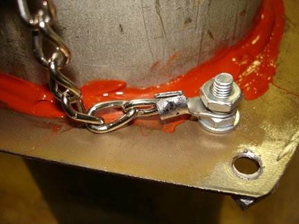 This photo shows how the other ends of the chains are attached to the bolts on the bottom of the flange. I used ring terminals crimped onto the
ends of the chains.
This photo shows how the other ends of the chains are attached to the bolts on the bottom of the flange. I used ring terminals crimped onto the
ends of the chains.
 With the internal parts all sorted out, it was time to button up the gasifier. Here I have mounted to central core assembly (flame tube, flange and grate)
and used liberal amounts of the high-temp silicone gasket material to seal up the unit. I could hardly wait for the silicone to cure so I could start the
test runs.
With the internal parts all sorted out, it was time to button up the gasifier. Here I have mounted to central core assembly (flame tube, flange and grate)
and used liberal amounts of the high-temp silicone gasket material to seal up the unit. I could hardly wait for the silicone to cure so I could start the
test runs.
 Here is the air blower I used to pull air through the gasifier. This blower last saw use in
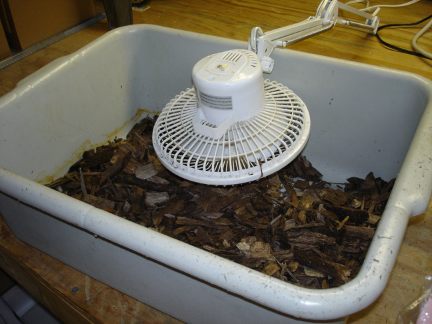 My dream fuel for the gasifier is free wood chips and mulch available from lots of places nearby. I know of at least three places I pass on a regular
basis that have signs offering free mulch to anyone who would come and haul it away. There are probably dozens of other sources I could find with a
little research. So I got myself a bag of wood chips. The chips were very wet. So here I am drying them with a fan. After 2 weeks under the fan, they
were bone dry and ready to burn in the gasifier. I realized that if this worked, I'd have to find a less energy intensive way of drying the wood chips
in the future.
My dream fuel for the gasifier is free wood chips and mulch available from lots of places nearby. I know of at least three places I pass on a regular
basis that have signs offering free mulch to anyone who would come and haul it away. There are probably dozens of other sources I could find with a
little research. So I got myself a bag of wood chips. The chips were very wet. So here I am drying them with a fan. After 2 weeks under the fan, they
were bone dry and ready to burn in the gasifier. I realized that if this worked, I'd have to find a less energy intensive way of drying the wood chips
in the future.
 Now it was time to give some thought to how to start up the gasifier. A lot of people build in a port in the side of their gasifier so they can stick a
blowtorch inside and start the fire. I decided to take a different approach. I decided to pre-load the reduction section of the gasifier with hot charcoal, and
then I'd fill the hopper up the rest of the way with whatever fuel I was going to burn. This starting procedure actually works quite well, and I have continued
to use it, even through all the redesigns and fuel changes the gasifier has gone through. With the reduction section full of hot charcoal, the reaction
starts almost immediately, and the gasifier (in its final design below) is producing good gas in only a couple of minutes.
Now it was time to give some thought to how to start up the gasifier. A lot of people build in a port in the side of their gasifier so they can stick a
blowtorch inside and start the fire. I decided to take a different approach. I decided to pre-load the reduction section of the gasifier with hot charcoal, and
then I'd fill the hopper up the rest of the way with whatever fuel I was going to burn. This starting procedure actually works quite well, and I have continued
to use it, even through all the redesigns and fuel changes the gasifier has gone through. With the reduction section full of hot charcoal, the reaction
starts almost immediately, and the gasifier (in its final design below) is producing good gas in only a couple of minutes.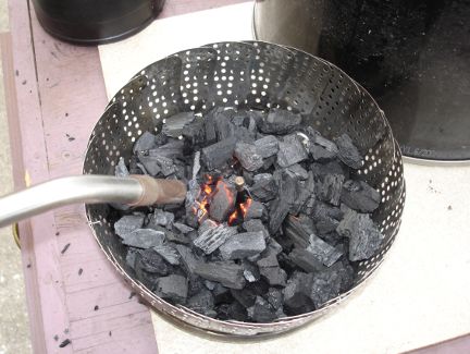 Here I am lighting the charcoal with my propane torch. The pulverized charcoal is in yet another stainless steel vegetable steamer. These things
are just so amazingly useful for so many non-vegetable steaming tasks. The small pieces of hardwood charcoal light easily and burn very hot. Only a
few quick passes from the torch gets them going. Once
the charcoal is good and hot, I dump it into the flame tube of the gasifier, and fill it up to the top of the reduction section. Then I fill the
flame tube up the rest of the way with fuel.
Here I am lighting the charcoal with my propane torch. The pulverized charcoal is in yet another stainless steel vegetable steamer. These things
are just so amazingly useful for so many non-vegetable steaming tasks. The small pieces of hardwood charcoal light easily and burn very hot. Only a
few quick passes from the torch gets them going. Once
the charcoal is good and hot, I dump it into the flame tube of the gasifier, and fill it up to the top of the reduction section. Then I fill the
flame tube up the rest of the way with fuel.
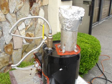 Here is a photo of the completed Mark I gasifier in operation. Ignore the hopper extension at the top of the flame tube. It was an experiment I tried
to increase the fuel capacity of the gasifier. I no longer use it. The aluminum foil is on top of it because it was raining a little bit, and I was
trying to keep the fuel dry.
Here is a photo of the completed Mark I gasifier in operation. Ignore the hopper extension at the top of the flame tube. It was an experiment I tried
to increase the fuel capacity of the gasifier. I no longer use it. The aluminum foil is on top of it because it was raining a little bit, and I was
trying to keep the fuel dry.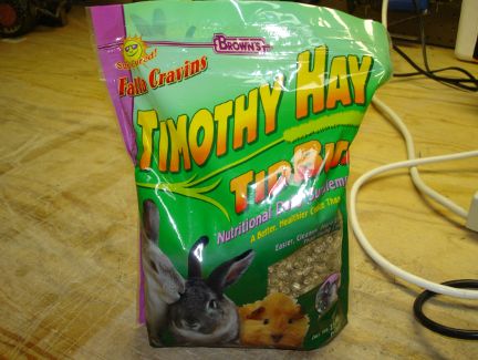 After doing some more research, (research I probably should have done up front), I came to realize that wood chips are a difficult fuel. The non uniform size
and shape of the chips makes them difficult to burn in a simple gasifier. So I switched fuels. I wanted to use wood pellets, but they are hard to find here
in Florida. So I settled on hay pellets. I could get them from feed stores, and they were reasonably priced. They seemed like a reasonable substitute for
wood pellets.
After doing some more research, (research I probably should have done up front), I came to realize that wood chips are a difficult fuel. The non uniform size
and shape of the chips makes them difficult to burn in a simple gasifier. So I switched fuels. I wanted to use wood pellets, but they are hard to find here
in Florida. So I settled on hay pellets. I could get them from feed stores, and they were reasonably priced. They seemed like a reasonable substitute for
wood pellets.
 So it was back to the drawing board. I knew that the easiest way to solve the zone migration problem was to cap the top of the flame tube. The flame was
simply moving up-wind toward the source of oxygen. Since the original design required air to move through the whole fuel column, the flame simply went
up the column toward the source of air and created the zone migration problem. Capping the tube meant I had to find a new way to get the air into the
gasifier.
So it was back to the drawing board. I knew that the easiest way to solve the zone migration problem was to cap the top of the flame tube. The flame was
simply moving up-wind toward the source of oxygen. Since the original design required air to move through the whole fuel column, the flame simply went
up the column toward the source of air and created the zone migration problem. Capping the tube meant I had to find a new way to get the air into the
gasifier.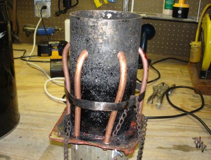 Here I have installed the six j-tubes. They are made of 3/8 inch copper tubing. They are called j-tubes because they are shaped like the letter J.
I used a large hose clamp cinched down tight to hold the tubes in place. The opening in the top of the drum needed to have a few notches cut in it
to accommodate a couple of the j-tubes that stuck out too far.
Here I have installed the six j-tubes. They are made of 3/8 inch copper tubing. They are called j-tubes because they are shaped like the letter J.
I used a large hose clamp cinched down tight to hold the tubes in place. The opening in the top of the drum needed to have a few notches cut in it
to accommodate a couple of the j-tubes that stuck out too far.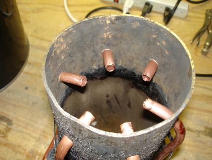 Here is a look up the bottom of the flame tube at the business ends of the j-tubes. Copper is probably not the ideal material to use here, since at least in
theory, the temperature at the point the air is injected could be high enough to melt them. So far my gasifier doesn't seem to get anywhere near that hot,
and the copper is holding up well. However, in my next gasifier, I will probably make at least the tips of the air inlets out of steel. Copper is just
so darn easy to bend and work with compared to steel tubing.
Here is a look up the bottom of the flame tube at the business ends of the j-tubes. Copper is probably not the ideal material to use here, since at least in
theory, the temperature at the point the air is injected could be high enough to melt them. So far my gasifier doesn't seem to get anywhere near that hot,
and the copper is holding up well. However, in my next gasifier, I will probably make at least the tips of the air inlets out of steel. Copper is just
so darn easy to bend and work with compared to steel tubing.
 Here is a view of the constrictor plate I made. By this point in the project I had my own welder (Yahoo!) and was getting proficient at using it. To make
the plate I cut a circle out of 1/8 inch sheet steel that would fit in the bottom of the flame tube. Then I cut a 2 1/2 inch diameter hole in the center
of the circle. To mount the constrictor in the flame tube, I welded three 1/4-20 nuts to the plate, and drilled passage holes in the flame tube for three
1/4-20 bolts.
Here is a view of the constrictor plate I made. By this point in the project I had my own welder (Yahoo!) and was getting proficient at using it. To make
the plate I cut a circle out of 1/8 inch sheet steel that would fit in the bottom of the flame tube. Then I cut a 2 1/2 inch diameter hole in the center
of the circle. To mount the constrictor in the flame tube, I welded three 1/4-20 nuts to the plate, and drilled passage holes in the flame tube for three
1/4-20 bolts.
 Here is a view of the constrictor plate installed in the bottom of the flame tube.
 Here I have installed the new shaker grate. I made it by cutting the bottom out of a stainless steel colander I bought cheap at a yard sale. The colander
already had a lot of holes in it, but I drilled quite a few more in it as well. It is suspended under the flame tube by the same four chains that held the
original steamer grate. I used the same system of attaching a length of stainless steel wire to one corner of the grate and running it outside the drum.
Tugging on the wire makes the grate shake and twist. It is not an ideal system, but it seems to work. I put a ring on the outside end of the wire to
make it easier to grip.
Here I have installed the new shaker grate. I made it by cutting the bottom out of a stainless steel colander I bought cheap at a yard sale. The colander
already had a lot of holes in it, but I drilled quite a few more in it as well. It is suspended under the flame tube by the same four chains that held the
original steamer grate. I used the same system of attaching a length of stainless steel wire to one corner of the grate and running it outside the drum.
Tugging on the wire makes the grate shake and twist. It is not an ideal system, but it seems to work. I put a ring on the outside end of the wire to
make it easier to grip.
 Here is a photo of the top of the re-assembled gasifier showing the tops of the j-tubes poking out of a sea of red silicone gasket material. It's a little
messy, but to me it was a thing of beauty.
Here is a photo of the top of the re-assembled gasifier showing the tops of the j-tubes poking out of a sea of red silicone gasket material. It's a little
messy, but to me it was a thing of beauty.
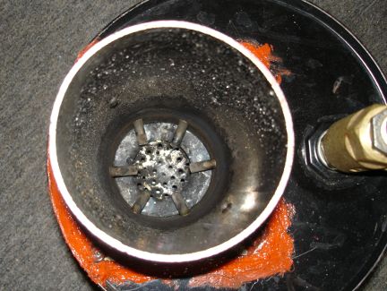 Here is a look down the flame tube of the new and improved design.
 Back to the drawing board again. While brainstorming on how to get compressed air into the gasifier, I noticed a steel air duct reduction fitting I had previously
used as an aborted attempt at a fuel hopper extension earlier in the project. I realized I could cut it down and make it a manifold that would cover the tops of all
six j-tubes. That would allow me to inject air into the system at only one point on the manifold and feed all six j-tubes. Brilliant, again, and this time it looked
foolproof. The manifold came together quickly.
Back to the drawing board again. While brainstorming on how to get compressed air into the gasifier, I noticed a steel air duct reduction fitting I had previously
used as an aborted attempt at a fuel hopper extension earlier in the project. I realized I could cut it down and make it a manifold that would cover the tops of all
six j-tubes. That would allow me to inject air into the system at only one point on the manifold and feed all six j-tubes. Brilliant, again, and this time it looked
foolproof. The manifold came together quickly.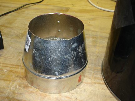 Here is the manifold I made to cover the inlets of all six j-tubes. It was cut from a 6 in to 4 in steel AC duct reduction fitting. It slips down over the
flame tube and gets siliconed to the top of the flange. A single air inlet fitting will be installed on the side of the manifold.
Here is the manifold I made to cover the inlets of all six j-tubes. It was cut from a 6 in to 4 in steel AC duct reduction fitting. It slips down over the
flame tube and gets siliconed to the top of the flange. A single air inlet fitting will be installed on the side of the manifold.
 Here is the new single air inlet on the side of the manifold. I used a Tee fitting. One leg of the Tee goes into the manifold. One leg has a hose fitting
installed that I can use to inject compressed air. The third leg of the tee is plugged for now. My idea here was that I could start the gasifier on
compressed air, then once it was running, I could unscrew the plug, and let engine vacuum pull air through the gasifier (from whatever engine the gasifier
eventually gets connected to).
Here is the new single air inlet on the side of the manifold. I used a Tee fitting. One leg of the Tee goes into the manifold. One leg has a hose fitting
installed that I can use to inject compressed air. The third leg of the tee is plugged for now. My idea here was that I could start the gasifier on
compressed air, then once it was running, I could unscrew the plug, and let engine vacuum pull air through the gasifier (from whatever engine the gasifier
eventually gets connected to).
 Here is the new and improved (again) gasifier, all buttoned up and sealed with yet more great gobs of red silicone gasket material, ready for a test
run. I couldn't wait to try it. So even though it was threatening rain, I set up the gasifier outside and fired it up.
Here is the new and improved (again) gasifier, all buttoned up and sealed with yet more great gobs of red silicone gasket material, ready for a test
run. I couldn't wait to try it. So even though it was threatening rain, I set up the gasifier outside and fired it up.
 I finally found some wood pellets. On one of my trips to Arizona, I bought two 40 pound bags of wood pellets. They were dirt cheap too.
Less than $6 per bag. I couldn't find them to save my life in Florida. Every hardware and homecenter store in Arizona seems to carry them though.
Now I have plenty of high quality fuel for testing out the new and improved (again) gasifier. Fortunately I drive
out to Arizona twice a year. So getting 80 pounds of wood pellets back home in my big truck was not a problem.
I finally found some wood pellets. On one of my trips to Arizona, I bought two 40 pound bags of wood pellets. They were dirt cheap too.
Less than $6 per bag. I couldn't find them to save my life in Florida. Every hardware and homecenter store in Arizona seems to carry them though.
Now I have plenty of high quality fuel for testing out the new and improved (again) gasifier. Fortunately I drive
out to Arizona twice a year. So getting 80 pounds of wood pellets back home in my big truck was not a problem.
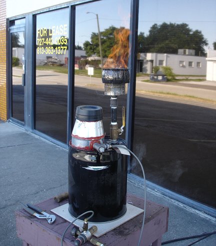
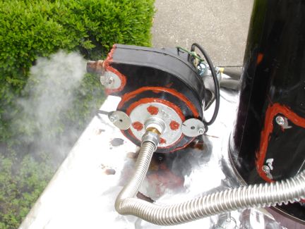
 At last! The gasifier was working well. It is making lots of gas and hardly any tar. Everything was working great. The gasifier was
producing such a huge volume of gas, I decided I needed a better way of flaring it off. So I bodged together a
quick and dirty gas burner. I just drilled a bunch of holes in the bottom of
an 18 ounce steel can, and bolted it on top of the gas outlet pipe. I then but the old stainless steel vegetable steamer I originally
used as a shaker grate over the open top of the can. It works great as a burner. The flame doesn't blow out even in very strong wind
gusts. I'll need to increase the stack height since the heat from the burner is starting to cook the rubber and silicone parts a little.
At last! The gasifier was working well. It is making lots of gas and hardly any tar. Everything was working great. The gasifier was
producing such a huge volume of gas, I decided I needed a better way of flaring it off. So I bodged together a
quick and dirty gas burner. I just drilled a bunch of holes in the bottom of
an 18 ounce steel can, and bolted it on top of the gas outlet pipe. I then but the old stainless steel vegetable steamer I originally
used as a shaker grate over the open top of the can. It works great as a burner. The flame doesn't blow out even in very strong wind
gusts. I'll need to increase the stack height since the heat from the burner is starting to cook the rubber and silicone parts a little.
 So here is my initial rough sketch of of a scrubber cooler system. My idea here is to use a water spray to clean up and cool the gas.
The gas would move up a column packed with either stones or golf balls, against the flow of water. The purpose of the packing material
is to increase the wet surface area the gas is exposed to as it passes up the scrubber column. The more surface area, the easier the gas
can give up its heat and suspended particles to the water.
So here is my initial rough sketch of of a scrubber cooler system. My idea here is to use a water spray to clean up and cool the gas.
The gas would move up a column packed with either stones or golf balls, against the flow of water. The purpose of the packing material
is to increase the wet surface area the gas is exposed to as it passes up the scrubber column. The more surface area, the easier the gas
can give up its heat and suspended particles to the water.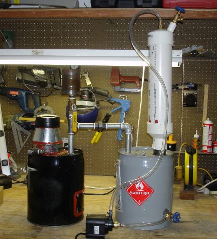 The results are in. And the answer is... It didn't work :-(