A New & Improved Charge Controller Based on the 555 Chip
A simple charge controller for solar and wind systems
UPDATE This 555 based solar charge controller project has won first place in the Utility Category of the
555 Design Contest!!!!!
Scroll to the bottom of the page for more information on the contest.
Several years ago I began building my own wind turbines and
solar panels to provide power on my remote, off-grid property. A charge controller is an
essential part of any wind or solar system to ensure the batteries aren't over or under charged. The charge controller monitors the battery
voltage and switches the batteries off charge when they are fully charged,
and switches them back on charge when they reach a pre-set level of discharge.
This is a new and improved charge controller design based on the 555 chip.
When I originally posted my home-built wind turbine, solar panel and charge
controller designs on the web, they became wildly popular. Lots of
people all over the world have built their own versions. I get flooded with emails every day from people with comments or questions. A very large
percentage of the emails concern problems people are having building the original charge controller design.
While the design is certainly more advanced than some middle school lesson plans in shop class,
it's certainly do-able for any reasonably skilled person.
The original charge controller design is still working after years of field use. Lots of people
all over the world have built copies of it. The original story of the development of this charge
controller can be found
on my wind turbine page.
Problem is, people with less electronics experience had trouble building it and getting it to work. The circuit was rather complex
and confusing for electronics beginners. Some people in far-flung parts of the world were having problems finding all the necessary parts.
The daily flood of emails requesting help with building the charge controller have prompted me to redesign it.
So I set myself the goal of greatly simplifying my solar/wind charge controller circuit. I wanted to get it down to only one
IC if possible, and reduce the number of other components as much as possible. I also wanted to make sure it only contained
easy to find components that should be obtainable pretty much anywhere in the world. That way maybe more people would be able
to build it without running into problems.
One of my friends suggested I switch to using one of the popular microcontroller chips and replace all the analog circuitry
with one chip. That would certainly get the parts count way down. However, I was worried that the microcontrollers
would be too expensive or difficult to obtain in some parts of the world, and too difficult for non-technical people to program. I decided to stick
with analog circuitry for now, though the microcontroller option is a possibility for the future.
Here is the schematic of my original charge controller circuit.
The heart of the charge controller circuit consists of a voltage divider, two comparators, and an S-R flip flop. My original
idea was to redesign it using the LM339 Quad Comparator IC. I'd need two of the comparators for this circuit, and could make an S-R
flip-flop using the other two left over comparators on the chip. I played around with this idea for a while, and
even bread-boarded a few test circuits. I was having some trouble getting it to work right though. So I shelved the project for a
while and worked on other things.
One other project I as working on was a PWM motor speed controller for the pump I use with my recirculating sluice box
that I use for gold prospecting.
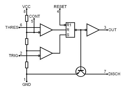
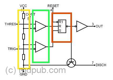
The speed controller uses a 555 timer chip. While looking at a diagram of the internal structure of the 555 chip, I was struck by how closely it
resembles my original charge controller circuit. Suddenly I realized I could redesign the charge controller circuit using the 555 chip and greatly
simplify the circuit and reduce the part count.
Compare the two diagrams on the left to see the similarities between my original charge controller circuit and the innards of the NE555 timer chip.
The colored boxes represent similar sections. The 555 timer could replace 7 components in the original circuit, and reduce the total complexity of
the circuit a whole lot. This is a very non-traditional and "off label" use of the 555 chip, since I'm not using it as a timer at all.
I'm co-opting it's internal organs for a completely different use than it was originally designed for.
Click to learn how
to meet them
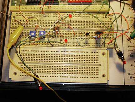
I set to work. In only a very short time, I had a working prototype circuit bread-boarded. It worked right the first try, which is rare for me. I almost always make
some sort of bone-head mistake wiring things up.
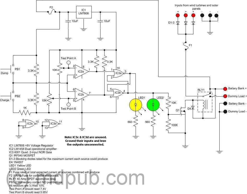
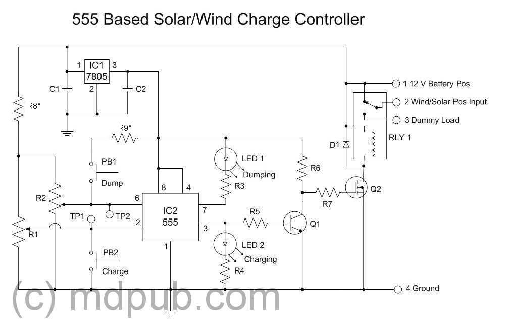
Here is a schematic of the new charge controller circuit. Click on it for a larger, clearer version.
I was careful to use only easy to find parts. The NE555 is probably the most popular IC in history. Billions of them are made every year. It should be
easy to find just about anywhere in the world. I also switched to a 5 Volt regulator from the 8 Volt regulator the earlier version used. People were complaining they
couldn't find it. The transistor is a 2N2222, NTE123, 2N3904, or other similar general purpose small NPN transistor. The MOSFET is an IRF540 or similar
power MOSFET. I just happen to have a bunch of IRF540s on hand, left over from other projects. So I used one of them rather than buying something else.
Use whatever you can find.
All the resistors are 1/8 watt. 1/4 watt or higher resistors can be substituted if you don't have 1/8 Watt resistors.
The two trimpots, R1 and R2, should ideally be multi-turn units, but ordinary single-turn units can be substituted, with a slight loss of precision
in the tuning. I used 10K trimpots because I already had them on hand. Any value between 10K and 100K ought to work just fine. 10% tolerance is plenty good
enough on all the passive components. There is no need for any precision parts in this circuit.
UPDATE
I have modified the above schematic by adding optional resistors R8* and R9*. These 330 Ohm resistors are not required to make the circuit work, but will help
protect against accidental short circuits if the trimpots are at the limits of travel and the push buttons are pressed, or if both push buttons are
pressed at the same time. My design here was deliberately minimalist and I omitted these safety resistors that were used on my earlier, more complex designs.
However, after making this design public, I decided it would probably be a good idea to add them back in so as to prevent accidents.
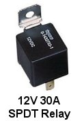
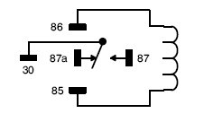
The relay is a
general purpose SPDT automotive relay rated at 40 amps. It should be very easy to find. Get one from an auto parts store, or salvage one from a junked
car in a scrap yard. I have included a pinout for the relay for ease of connection. 40 Amps may seem like overkill, but it allows for expansion in the
future. You may start with only one small solar panel, then add a few more later, possibly a wind turbine, and a bigger battery bank. Eventually the
charge controller will need to switch some serious current. Why not build in the capability from day one? All other parts are specified below.
Most of the parts can be purchased at your local Radio Shack, or purchased online at Newark/Element 14,
or sourced through Amazon.com or Ebay.com, or if you are lucky enough to have an old-timey electronics store nearby.
The rest of the parts can be found at auto parts stores.
You might find the online suppliers to be much cheaper, especially if you plan on building several units and need multiples of each part. You
could also try looking for deals on parts on Amazon.com. I buy my automotive relays on Ebay. Even with shipping it is cheaper than the auto parts store,
and they are delivered right to my mail box.
IC1 - 7805 5 Volt positive Voltage Regulator
R3, R4, R5 - 1K Ohm 1/8 Watt 10%
IC2 - NE555 Timer Chip
R6 - 330 Ohm 1/8 Watt 10%
PB1, PB2 - NO Momentary Contact Push Buttons
R7 - 100 Ohm 1/8 Watt 10%
LED1 - Green LED
Q1 - 2N2222 Or Similar NPN Transistor
LED2 - Yellow LED
Q2 - IRF540 Or Similar Power MOSFET
RLY1 - 40 Amp SPDT Automotive Relay
C1 - 0.33uF 35V 10%
D1 - 1N4001 or similar
C2 - 0.1uF 35V 10%
R1, R2 - 10K Multi-Turn Trim-Pots
R8*-R9* - Optional 330 Ohm 1/2 W Resistors (see text)
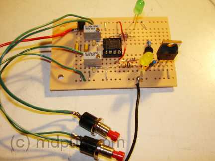
Once I had the prototype working on the breadboard, I built another unit on a piece of Radio Shack Protoboard for use in the field.
It came together in only a couple of hours, and again, worked the first time (I must be living right lately). This more rugged version
will get mounted in a box and given a thorough testing in the field.
Note that on this board I have chosen to use the 78L05 version of the 5 Volt regulator. It is in a tiny TO-92 package, the same size as the 2N2222 transistor.
It is the small, black rectangle on the upper left corner of the board. It saves a lot of board space. It can only handle 100 mA, but that is
plenty enough to power this circuit. If you can't find the little 78L05, you can use the full size TO-220 version of the 7805, which is much more
common. There will be no penalty other than using up a little more board real estate. I just happened to have a few of the 78L05s left over
from another project.
Once you have the circuit built, it is time to tune or calibrate it. I use 11.9V and 14.9V as my low and high set points for the controller.
These are the points where it switches from sending power to the batteries to dumping power into a dummy load, and vice versa (a dummy load
is only needed if you are using a wind turbine, if using only solar panels, the dummy load line can be left open).
Probably the best way to tune the circuit is to attach a variable DC power supply to the battery terminals. Set the power supply to 11.9V.
Measure the voltage at Test Point 1. Adjust R1 until the voltage at the test point is as close to 1.667V as you can get it. Now set
your variable power supply to 14.9V and measure the voltage at Test Point 2. Adjust R2 until the voltage at the
test point is as close to 3.333V as you can get it.
Test the operation of the charge controller by running the input voltage up and down between about 11.7 and 15.1 Volts. You should hear the relay
pull in at about 14.9 Volts and open at about 11.9 Volts. In between the two set points the controller should stay in whichever state it is in. The
Charge and Dump buttons can be used to change the state of the controller when the input Voltage is between the two set points.
Before you write to me and tell me that my lower set point is too low and I am over-discharging my batteries, consider that the battery voltage isn't normally
going to get that low except under load. If the load were removed, the voltage would recover over time back up to well over 12V. So the batteries aren't as
deeply discharged as you might think at first glance. Also, the high voltage limit will be different for different battery types, like flooded vs AGM. Consult
the spec sheet for your particular type of battery.
UPDATE
People are writing me and asking if this charge controller can be used with 24 Volt systems, and what changes would be necessary.
The circuit should work fine for 24 Volt systems.
The relay will need to be replaced with one rated for 24V coil voltage, and the pots will have to be re-calibrated for new high and low
set points for the higher battery Voltage. The 7805 Voltage regulator is rated for up to 35 Volts input Voltage, so no other changes in the
circuit should be necessary other than re-tuning.
Use with other battery Voltages: As for using this circuit with other battery voltages, I can only say maybe. You need to keep a few things in mind. The 7805 voltage regulator
is rated for a maximum input Voltage of 35V. The minimum Voltage it needs to operate correctly is around 7V. So the circuit in theory should be able to operate
correctly anywhere between those upper and lower limits, IF you can find a relay with a compatible coil Voltage. That actually shouldn't be too
much of a problem for common battery Voltages.
Notes on tuning: I get a lot of questions about how to tune the circuit for different Voltages and why it needs to be tuned the way I do it. It is actually pretty simple.
A quick look at the 555 spec sheet will show that the circuit will switch to charging if the input Voltage on pin 2 falls lower than 1/3 of the supply Voltage. Since the supply
Voltage is 5V, 1/3 of that is about 1.6667V. So that is what you need to tune TP1 to while putting your lower limit Voltage on the battery input with a variable DC
power supply. Similarly, the circuit will switch to dumping if the input Voltage on pin 8 goes above 2/3 of the supply voltage, or 3.3333V in our case. So that is
what you need to tune TP2 to while putting your upper limit Voltage on the battery input. Simple really.
Click to learn how
to meet them
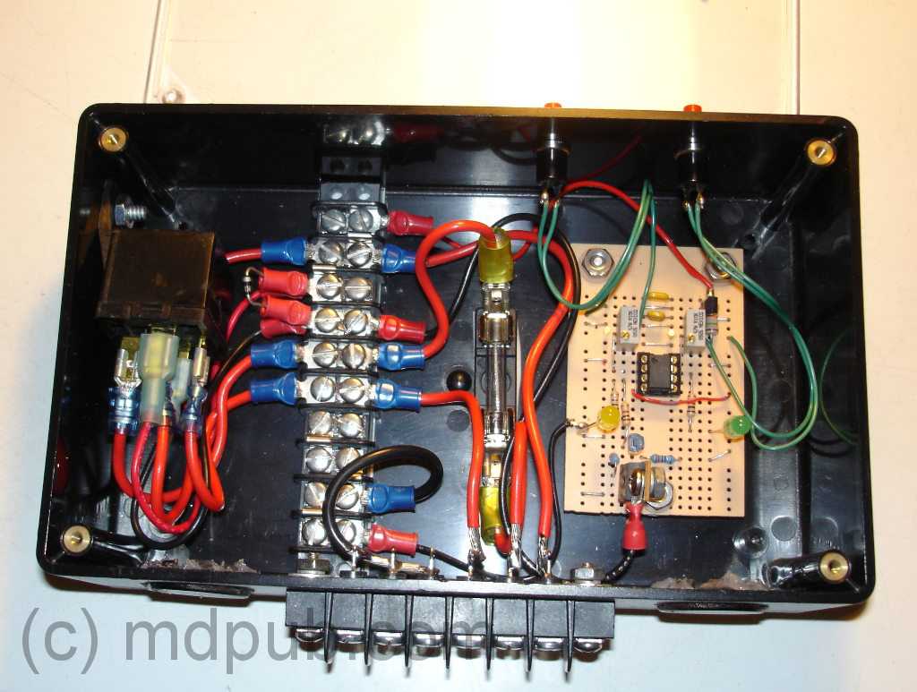
Once I had the circuit working, I mounted it inside a semi-weatherproof enclosure. The relay is on the left side.
I used a barrier strip to make wiring everything together easier. I used heavy gage wire for all the high-current connections. This thing
was designed to switch up to 40 Amps after all. I also included a fuse in line with the solar/wind input line.
Click on the image for a larger view.
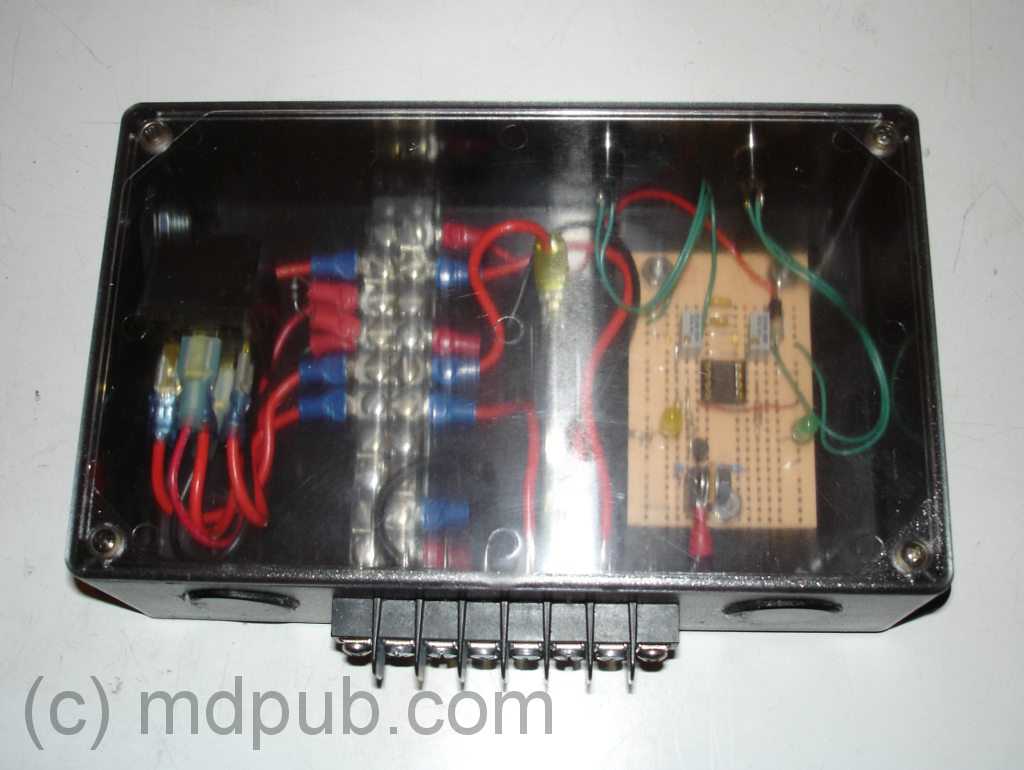
Here is another view with the lid in place. I used this enclosure because I happened to already have it on hand,
not because it is the best one for
the job. For permanent outdoor use I would prefer to use a more rugged and weather-proof enclosure like I did for
my original charge controller design. However, I like the fact that I can see the LEDs through
the translucent lid and tell which state the charge controller is in at a glance, and I didn't have to drill any extra holes in the box for the LEDs.
This box will work for field testing purposes.
Click on the image for a larger view.
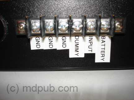
Here is a side view of the unit showing the feed-through barrier strip with all the connections to the outside. There are connections for the positive side
of the battery(s), the positive input from a solar panel or wind turbine, the positive side of an optional dummy load, and three ground connections.
When hooking up the charge controller, the battery should be connected first. That way the electronics will have a stable source of power. If a
solar panel or wind turbine is connected first, the controller is liable to wildly oscillate between states.
I should explain about dummy loads. The type of wind turbines I build have no real provision for
braking or furling in high winds. It is only the presence
of a constant load on them that prevents them from over-reving in high winds. So when the charge controller senses that the batteries are fully charged and
switches them out of the circuit, it switches in a dummy load (just a big external bank of high-wattage resistors) to soak up the power output
of the wind turbine and keep it under load. If you are using a commercially made wind turbine with built-in over-rev protection, or using only solar panels,
then the dummy load isn't necessary and you can leave the dummy line unconnected. You can learn more about dummy loads on
my wind turbine page.
Here is another side view showing the charge and dump buttons. The charge controller will automatically switch between charge and dump
when the battery voltage reaches the low and high set points. Between the set points the controller will remain in whichever state it
is in. These buttons allow me to manually toggle the charge controller between the two states.
Click to learn how
to meet them
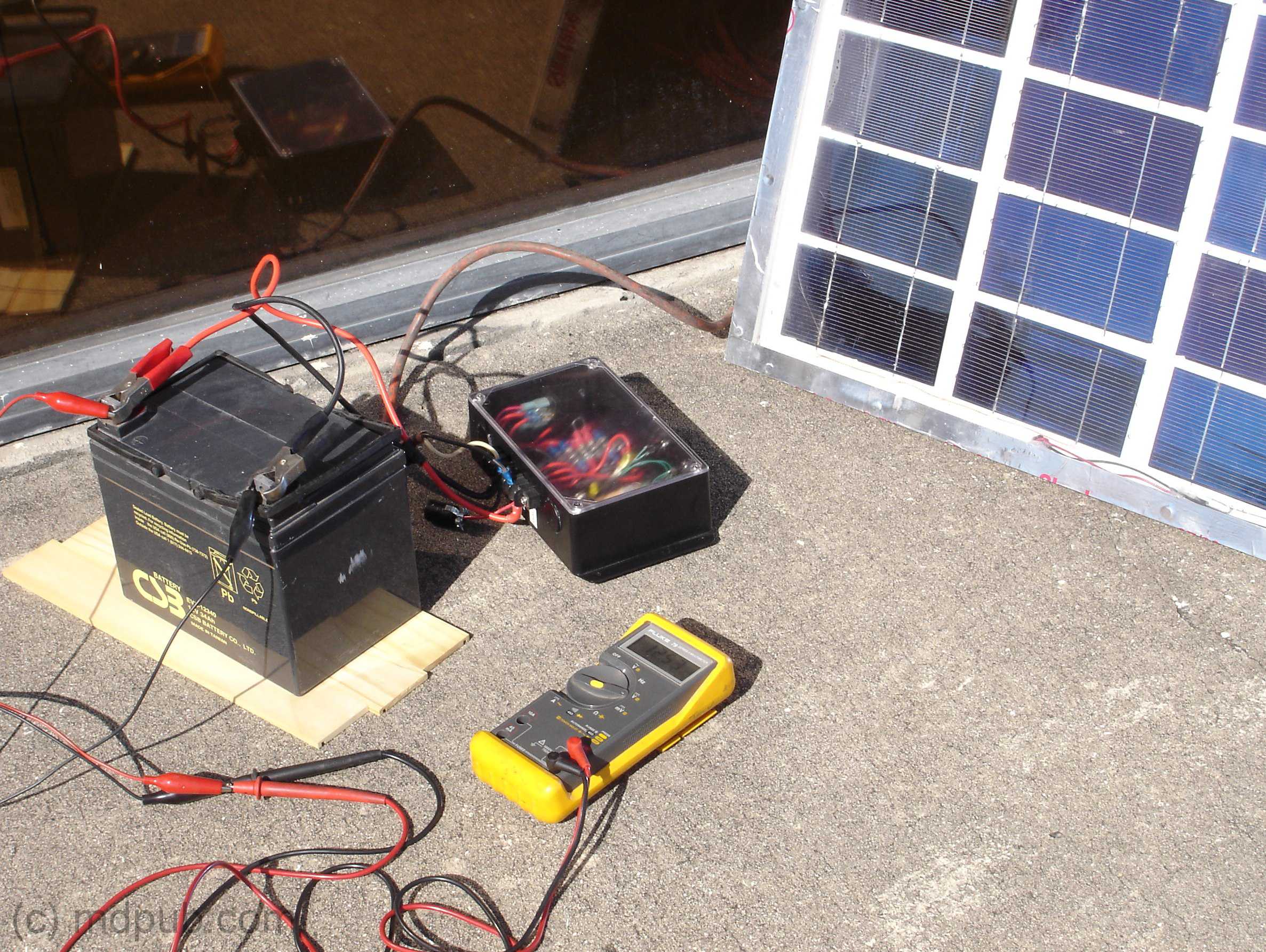
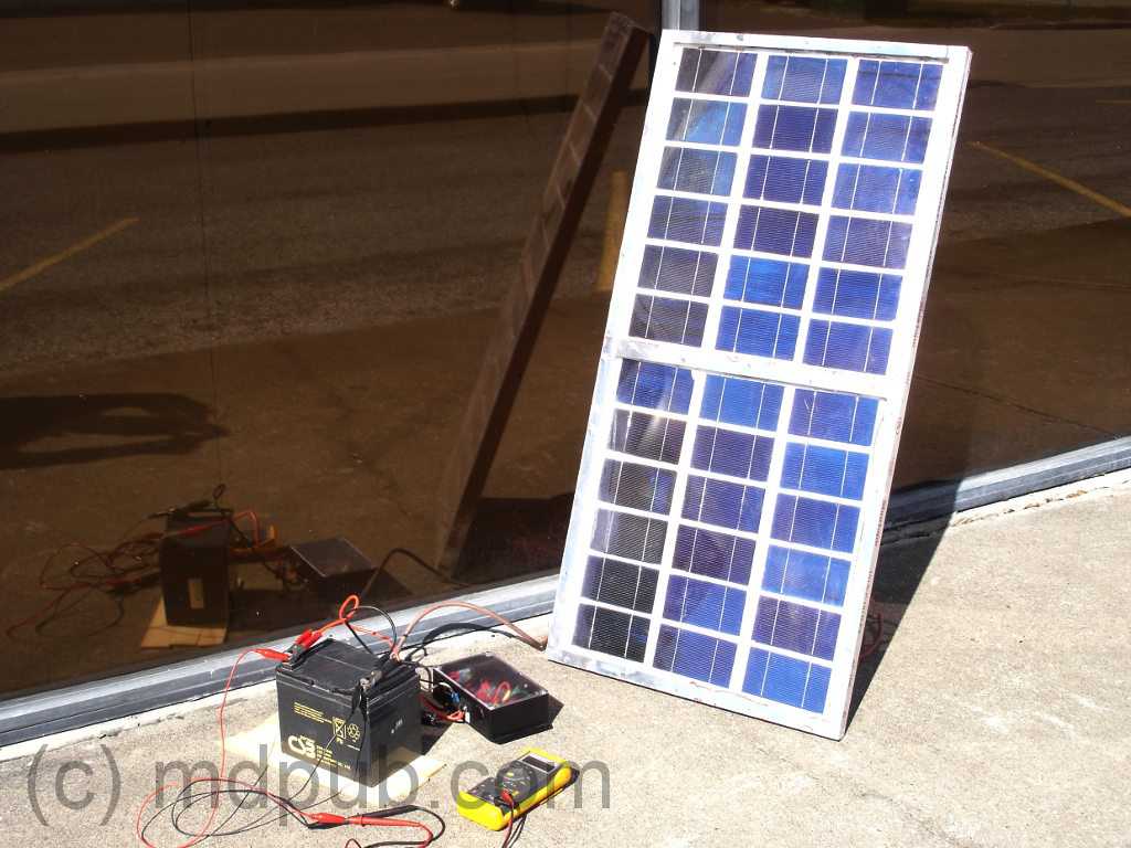
Here is a photo of the first real field test of the new charge controller design. It seemed to be working good in my bench tests, but
I wanted to make sure it worked right under real-world conditions. So I set up one of my home-made
60 Watt solar panels outside my
workshop and used it to charge up a deep-cycle battery using the new charge controller. It worked great. The charge controller let power
run into the battery until it was fully charged and then switched to dumping power so as not to over-charge the battery. Perfect!
Click on the photo for a larger version.
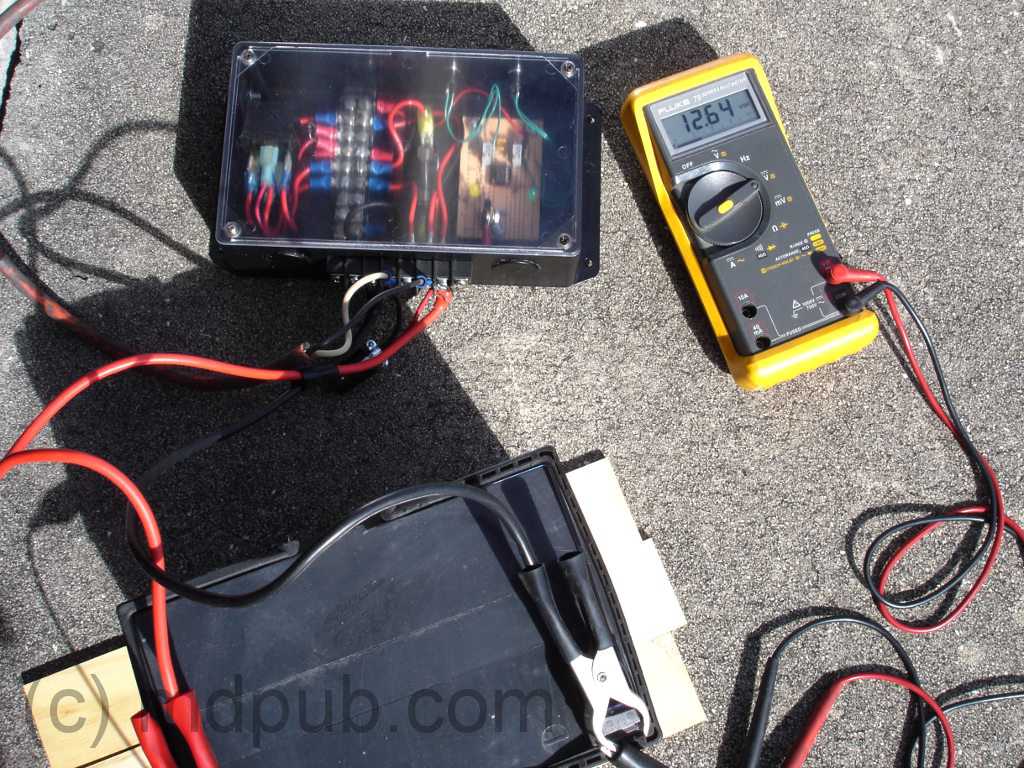
Here is a closer photo of the setup. The battery is a 36 AH deep-cycle unit often used in personal mobility scooters and motorized wheel chairs. I find
that they work well in small-scale wind and solar power systems. The Volt meter
is showing 12.64 volts on the battery, which is essentially fully charged. The battery was nearly fully charged when I started this test. It took only
a short time for the solar panel to top it off and the charge controller to switch over to dumping. A highly successful test.
The only issue I had during the test was seeing which of the LEDs was on in the bright sunlight. In normal use though the charge controller
would be mounted in a sheltered and shady spot out of the direct sunlight.
Click on the photo for a larger version.
Here is a brief video I shot during the test run. It shows how the charge controller automatically switches over from charging to
dumping when the upper set point is reached.
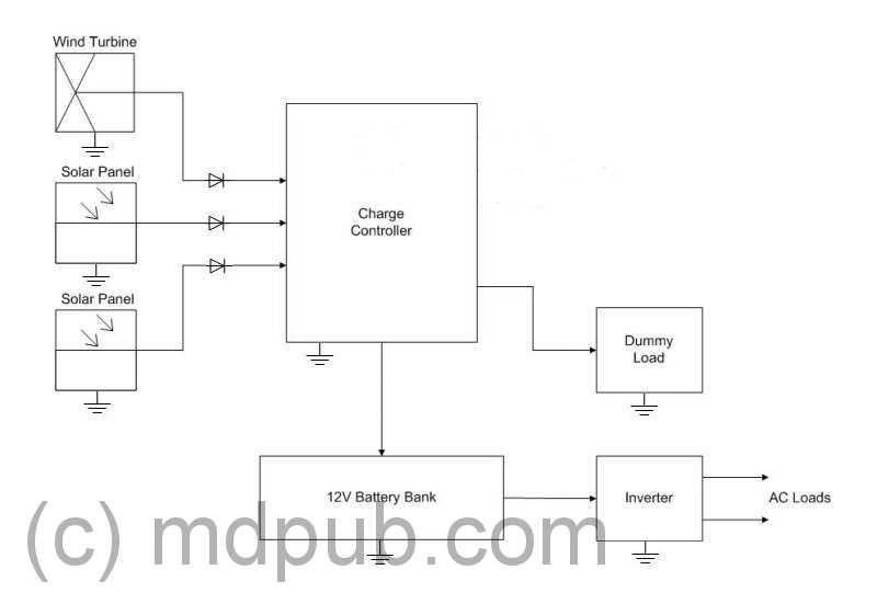
Multiple solar panels and/or wind turbines can be connected to this unit. All the power sources can be connected in parallel and fed into the single input
connection. Each individual solar panel or wind turbine needs to have its own blocking diode though. Here is a diagram of a typical system with a wind turbine
and two solar panels feeding the charge controller. Typically an AC inverter is included in the system to power AC loads. Click on the image for a larger version.
People write me and ask why they need a charge controller and batteries? Why not just connect the solar panel or wind turbine directly to the inverter and be
done with it? Well, the answer is that the sun doesn't always shine and the wind doesn't always blow, but people want power anytime. The batteries store power
when it is available, for use when it is needed.
I may develop a printed circuit board for this project, if time permits and there is sufficient interest. I'll post further updates
on this project as it progresses.
Click to learn how
to meet them
UPDATE
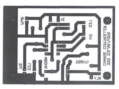
My friend Jason Markham has created a PC Board layout for this project almost as soon as I posted it.
Click the PCB to go to his web site.
UPDATE
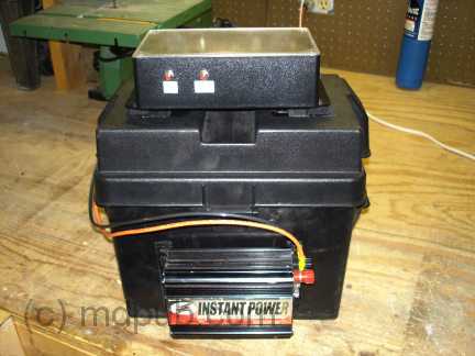
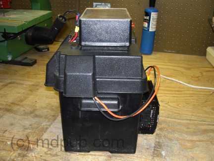
In an effort to create a compact, neat and portable solar power system, I have mounted the charge controller on top of a battery box. I have also mounted an
AC inverter on the box. This is a much larger and higher capacity battery than I was using in my early tests of the charge controller. The
inverter and charge controller are mounted on the battery box with industrial strength, sticky-back Velcro.
Here is another view of the setup. As you can see, I have also included a cigarette lighter style plug for powering 12V DC loads. It is a
complete solar power system in one small (but heavy) package. All I have to do is connect a solar panel or two to it. I can't wait to try it
out on my next camping trip. I'll have plenty of power in the wilderness.
I have finally decided to ditch my old battery bank, which I had been lugging around on my wilderness outings for years. It was a bank of 14 smaller 12V
AGM batteries. I got the batteries essentially for free, so I wired them in parallel, put them in a plastic bin, and used them with my portable
solar/wind power system. The setup was very heavy and unwieldy. I kept telling myself I'd get rid of it and go with one big battery once
the little batteries started dying. They hung on for years and years. I must have been treating them right. Finally they started loosing capacity
and dying off one by one. So I went out and bought one big battery to replace them all. It is about the same size and weight as a car battery,
but it is a deep-cycle design, perfect for solar/wind systems. It has about the same AH capacity as the old bank of 14, but
is much smaller and quite a bit lighter. It only set me back about $200. If it lasts as many years as the old bank, I'll be very happy. My back will
also be happy that I don't have to lift the old bank of 14 batteries anymore.
UPDATE
This 555 based solar charge controller project has won first place in the Utility Category of the 555 Design Contest!!!!! Yahooooo!
For anyone interested,
here is a Youtube video of Chris Gammell and Jeri Ellsworth announcing the 555 contest winners. The bit where they talk this project at about the
47 minute mark.
Just to clear up one detail mentioned in the video, this project was not actually created to be a contest entry. I had already had my "Eureka
Moment" about using the 555 to replace a whole bunch of parts in the original design, and was building the prototype before I even heard about
the 555 Contest. It just turned out to be great accidental timing. Hearing about the contest did spur me to quickly finish the prototype and get this web
page up in a timely manner though.
Many thanks to Jeri, Chris, the other judges, and the sponsors of the contest.
UPDATE
Something really cool happened today. I got an email from Chris Hackett from the Science Channel TV show Stuck With Hackett. He used
my 555 Based Charge Controller Design in one of his builds in a Youtube video. He built a bike
powered generator for recharging batteries and needed a charge controller. He was inspired to build his generator by the power outages
after Superstorm Sandy. I have embedded the video here.

 One other project I as working on was a PWM motor speed controller for the pump I use with
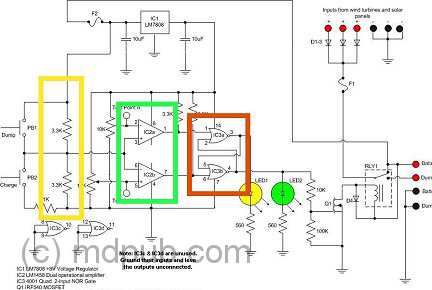
 I set to work. In only a very short time, I had a working prototype circuit bread-boarded. It worked right the first try, which is rare for me. I almost always make
some sort of bone-head mistake wiring things up.
I set to work. In only a very short time, I had a working prototype circuit bread-boarded. It worked right the first try, which is rare for me. I almost always make
some sort of bone-head mistake wiring things up.
 The relay is a
general purpose SPDT automotive relay rated at 40 amps. It should be very easy to find. Get one from an auto parts store, or salvage one from a junked
car in a scrap yard. I have included a pinout for the relay for ease of connection. 40 Amps may seem like overkill, but it allows for expansion in the
future. You may start with only one small solar panel, then add a few more later, possibly a wind turbine, and a bigger battery bank. Eventually the
charge controller will need to switch some serious current. Why not build in the capability from day one? All other parts are specified below.
The relay is a
general purpose SPDT automotive relay rated at 40 amps. It should be very easy to find. Get one from an auto parts store, or salvage one from a junked
car in a scrap yard. I have included a pinout for the relay for ease of connection. 40 Amps may seem like overkill, but it allows for expansion in the
future. You may start with only one small solar panel, then add a few more later, possibly a wind turbine, and a bigger battery bank. Eventually the
charge controller will need to switch some serious current. Why not build in the capability from day one? All other parts are specified below.
 Once I had the prototype working on the breadboard, I built another unit on a piece of Radio Shack Protoboard for use in the field.
It came together in only a couple of hours, and again, worked the first time (I must be living right lately). This more rugged version
will get mounted in a box and given a thorough testing in the field.
Once I had the prototype working on the breadboard, I built another unit on a piece of Radio Shack Protoboard for use in the field.
It came together in only a couple of hours, and again, worked the first time (I must be living right lately). This more rugged version
will get mounted in a box and given a thorough testing in the field.
 Here is a side view of the unit showing the feed-through barrier strip with all the connections to the outside. There are connections for the positive side
of the battery(s), the positive input from a solar panel or wind turbine, the positive side of an optional dummy load, and three ground connections.
Here is a side view of the unit showing the feed-through barrier strip with all the connections to the outside. There are connections for the positive side
of the battery(s), the positive input from a solar panel or wind turbine, the positive side of an optional dummy load, and three ground connections.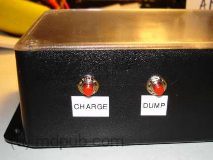 Here is another side view showing the charge and dump buttons. The charge controller will automatically switch between charge and dump
when the battery voltage reaches the low and high set points. Between the set points the controller will remain in whichever state it
is in. These buttons allow me to manually toggle the charge controller between the two states.
Here is another side view showing the charge and dump buttons. The charge controller will automatically switch between charge and dump
when the battery voltage reaches the low and high set points. Between the set points the controller will remain in whichever state it
is in. These buttons allow me to manually toggle the charge controller between the two states.
 UPDATE
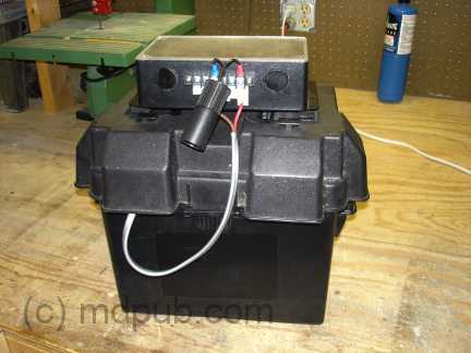 Here is another view of the setup. As you can see, I have also included a cigarette lighter style plug for powering 12V DC loads. It is a
complete solar power system in one small (but heavy) package. All I have to do is connect a solar panel or two to it. I can't wait to try it
out on my next camping trip. I'll have plenty of power in the wilderness.
Here is another view of the setup. As you can see, I have also included a cigarette lighter style plug for powering 12V DC loads. It is a
complete solar power system in one small (but heavy) package. All I have to do is connect a solar panel or two to it. I can't wait to try it
out on my next camping trip. I'll have plenty of power in the wilderness.
 I have finally decided to ditch my old battery bank, which I had been lugging around on my wilderness outings for years. It was a bank of 14 smaller 12V
AGM batteries. I got the batteries essentially for free, so I wired them in parallel, put them in a plastic bin, and used them with my portable
solar/wind power system. The setup was very heavy and unwieldy. I kept telling myself I'd get rid of it and go with one big battery once
the little batteries started dying. They hung on for years and years. I must have been treating them right. Finally they started loosing capacity
and dying off one by one. So I went out and bought one big battery to replace them all. It is about the same size and weight as a car battery,
but it is a deep-cycle design, perfect for solar/wind systems. It has about the same AH capacity as the old bank of 14, but
is much smaller and quite a bit lighter. It only set me back about $200. If it lasts as many years as the old bank, I'll be very happy. My back will
also be happy that I don't have to lift the old bank of 14 batteries anymore.
I have finally decided to ditch my old battery bank, which I had been lugging around on my wilderness outings for years. It was a bank of 14 smaller 12V
AGM batteries. I got the batteries essentially for free, so I wired them in parallel, put them in a plastic bin, and used them with my portable
solar/wind power system. The setup was very heavy and unwieldy. I kept telling myself I'd get rid of it and go with one big battery once
the little batteries started dying. They hung on for years and years. I must have been treating them right. Finally they started loosing capacity
and dying off one by one. So I went out and bought one big battery to replace them all. It is about the same size and weight as a car battery,
but it is a deep-cycle design, perfect for solar/wind systems. It has about the same AH capacity as the old bank of 14, but
is much smaller and quite a bit lighter. It only set me back about $200. If it lasts as many years as the old bank, I'll be very happy. My back will
also be happy that I don't have to lift the old bank of 14 batteries anymore.