A video of equatorial platform being set up at the 2010 Orange Blossom Star Party.
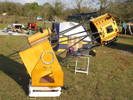
Here is a photo of the 17.5 inch Dobsonian telescope on my new equatorial platform. Here the scope is set up at the
Orange Blossom Special Star Party at Alafia River State Park in February 2006. It was the first real test of the
platform (outside my back yard). All though I had built it specifically for use with the big Dob, I had not yet
had a chance to actually test it with anything as heavy as the big Dob. It was only finished a few days before the
star party and I had only tested it with one of my much smaller scopes. I was a little worried about whether it would
really work with all that weight sitting on it. If anything it seems to work even better and more smoothly with
the larger load of the big Dob.
Here's another view of the scope sitting on the equatorial platform. Having an equatorial platform is a big help
when I am at a public observing event and I have a long line of people at the telescope wanting to see the
wonders of the universe. I can put the scope on an object (even at really high power) and just walk away. The
platform will do the work for me. Dozens of people can get a good long look through the scope without my having
to jump in after every person or two and re-aim the telescope as the Earth rotates the object out of interest
out of view. Below are some close-up photos of the platform.
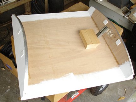
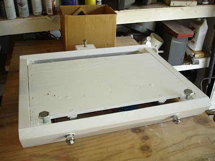
Here is a view of the platform without the telescope sitting on it. The top is 24 inches square. The three pads of
carpet help prevent vibration from the drive motor exciting the telescope. Here it is in the middle of its range of
travel and the top is flat. This is the best position for setting up the telescope on top of it. After the scope is
set up, the platform is reset to it's extreme Easterly position. The platform was built to work at 30 degrees North latitude.
this is a good compromise since I will be using it both in Florida and Arizona. In Florida the North end needs to be
tilted down a couple of degrees. In Arizona it needs to be tilted up a few degrees. There are three levelling feet on the
underside that allow me to level and tilt the platform as needed for a perfect alignment. A small bubble level and a
compass are all the tools I need for alignment.
How did I design this platform? Here are a series of drawings that show the mental process I went through to come up with this design. I need to
warn anyone thinking of copying this platform that the design must be modified for your particular latitude. My platform was designed to work
in Central Florida. The same design won't work for someone significantly North or South of 28 degrees North latitude, without rework. So I
am going to show you how to design your own platform for your particular area. Note: These instructions should work just as well in the Southern
Hemisphere if North and South are reversed in the diagrams, and the motor drive direction is reversed.
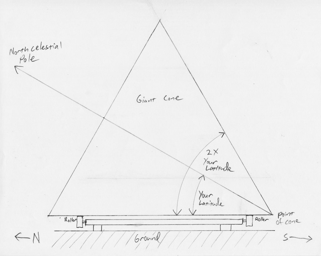
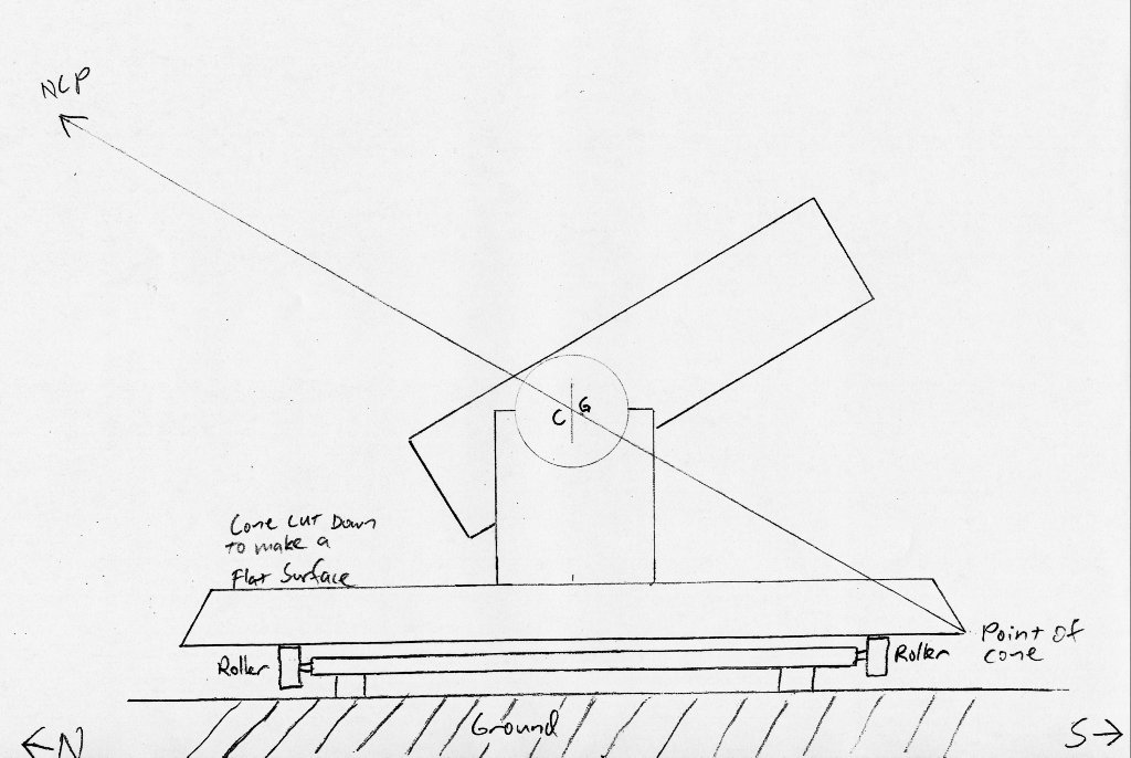
I spent a long time brainstorming how to do this. One mental image I coming back to over and over again was the idea of a cone on rollers.
Imagine a giant cone lying on the ground with the point facing due South. If the half-angle of the cone is equal to your latitude, then
the axis of the cone should point to the North Celestial Pole.
Now put the cone on a set of roller wheels that support it with the tip still pointing due South, and the bottom side parallel to the ground.
if the cone is rotated clockwise (as seen from the North side) at the sidereal rate of one revolution per day, the Earth's rotation would be cancelled
out, from the point of view of the cone, and any camera or telescope attached to the cone should follow the stars.
Click on any drawing for a larger view.
The cone shape is pretty inconvenient for mounting cameras and telescopes to. So I next imagined slicing off most of the cone parallel
to the ground to provide a flat surface to mount a telescope on. The cone can no longer rotate a full 360 degrees. It can now only rotate
through a few degrees either side of center before we run off the rollers. So in use, the platform will be run clockwise for some period of time,
(about 40 minutes in my case), then it must be reset back to the fully counterclockwise position. The drive motor can be run much faster
than the sidereal rate when resetting to make the wait until the platform can be used again quite short.
If the platform is designed in such a way that the axis of the (now virtual) cone passes through the center of gravity of your telescope, the system
will be very nearly balanced, and very little torque will be required to drive the platform, even with outrageously heavy telescopes like my
massive 17.5 inch dob. Note that I made a mistake in these drawings and have the axis passing through the CG of the tube assembly. The actual center of gravity of
the whole telescope, including rocker box and ground board, is really lower than this. Keep that in mind.
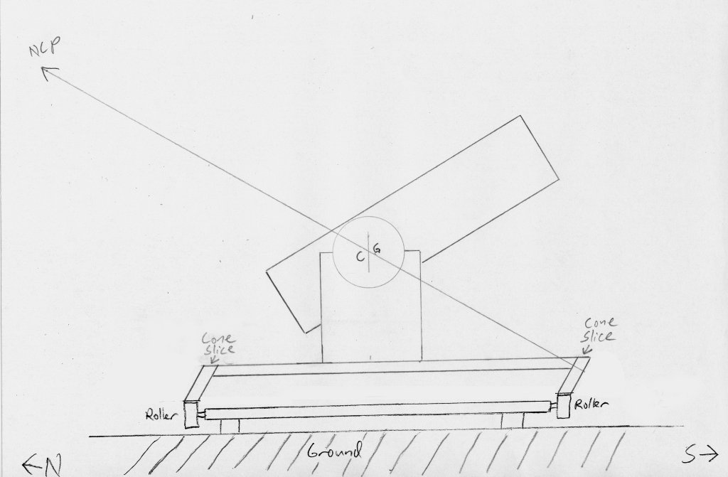
My next imaginary leap was to realize that only the parts of the cone riding against the rollers needed to follow the shape of the cone. The entire rest of the cone
could be cut away. Now only two slices or sectors out of the original cone are left to ride against the rollers and the rest of the platform is just a flat plate.
The physical point of the cone is now gone and only exists virtually out in space South of the platform.
At this point I was about to start building. I had a design that I was sure would work and that I felt sure I could build. The only fly in the ointment
was the cutting the correct curves and angles on the sectors. I was already pretty good at cutting straight-sided circles out of plywood. However, cutting
the sectors at the angle of the cone was a new twist. I realized I was going to have to design and build some sort of special jig to do it. This prompted
me to think about how to simplify the design a little more.
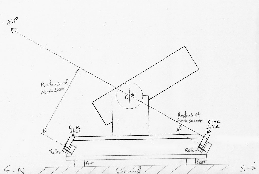
The final revelation was changing my vision of the cone from a perfect straight-sided cone, to a stack of short cylinders of different diameters,
like in the Towers of Hanoi game.
Now each sector is a slice out of a straight-sided cylinder with a radius equal to its distance from the axis of the virtual cone. The rollers would
be mounted on supports tilted at the angle of latitude. Not only does this simplify making the sectors, but the design change also provides constraint
on the motion of the platform and prevents it from running off the rollers to the North or South.
A simple way to size everything is to find the height of the center of gravity of your telescope, and make a drawing to scale with the line pointing to the NGP
passing through the centerline of the top plate at that height. Then just take measurements off the drawing for the radii of the sectors. Note that
these particular drawings are just for illustration and are not to scale, and my own sector raddi and heights are different. On my platform the North
sector has a radius of 35 inches and the South sector is 24 inches. Both have a height of 4 inches.
Now I was ready to build
While still on the subject of initial design considerations, I should point out that there are several possible methods of driving the platform.
Two that immediately come to mind are using a driven wheel in place of one of the idler rollers, or using a linear rack system with a pin that engages
a slot attached to the top plate. I chose the latter system, even though it is considerably more complicated. I was concerned that a drive wheel might not
be able to transmit enough torque in an out of balance situation and might slip, especially when wet with dew. A driven wheel might work just fine in your
application. Food for thought.
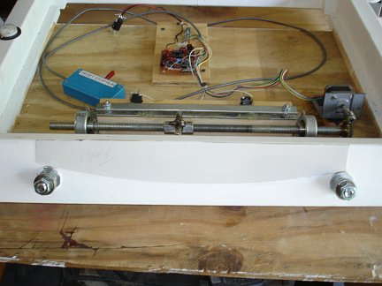
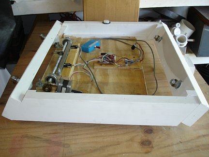
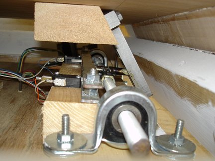
Here is an overview of the equatorial platform as seen from the North side with the top plate removed. I'll go into some
of the details about how it works below. Here is an
overview. A stepper motor turns a worm gear which turns a piece of half inch threaded rod. There is a nut with a steel
pin welded to it that travels left to right on the threaded rod as it rotates. The pin engages a slotted tab on the underside
of the top plate and drags it along. The top plate sits on sectors which ride on tilted bearings which point through
the North Celestial Pole. The platform will run for 40 minutes before the pin on the nut hits the West limit switch and
shuts the motor down. Another limit switch on the East side shuts the motor down at the end of a reset cycle.
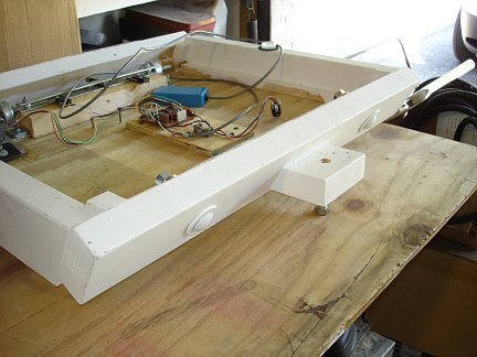
Here is another overview of the platform from the side with the top plate removed. The North side is on the left and the South
side is on the right. As you can see, the North and South sides are tilted up at 30 degrees. The bearings on the South side
are inside the base. The bearings on the North side are on the outside of the base. The frame of the base unit is made from
2X4s. The 2X4s are screwed together with long wood screws. The corners are reinforced with wood glue blocks. A plywood panel
screwed onto the bottom provides a platform for the drive system and further reinforces the frame by preventing it from skewing
out of square. The bearings are 1 inch
diameter sealed ball bearing units with 1/2 inch bores. They are mounted on 1/2 inch carriage bolts which pass through the
2X4 frame on the North and South sides. Formica crescents are glued on the North and South faces between the ball bearings.
GoreTex pads on the backs of the plywood sectors of the top plate ride against the Formica creating another bearing surface.
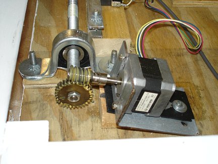
Here's a close-up of the drive motor and gearing. A 200 step/rev stepper motor salvaged from an old disk drive is half-stepped at
375 steps per second. Half stepping reduces vibration. The motor is mounted on rubber pads to further damp out vibration. The
motor turns a 30:1 ratio worm gear, which is attached to the end of the main threaded drive rod. Everything about this layout is
about reducing and damping out vibration from the motor. The half stepping and the 30:1 ratio mean that the motor must be stepped
very fast. Fast steps mean a high frequency vibration that damps out much more easily than slower clunk-clunk-clunk type steps if the
motor were coupled directly to the threaded rod. The 30:1 gear ratio also means that a much smaller motor can be used to drive the
platform. A smaller motor means - you guessed it - less vibration. If I had it to do over I'd probably try to use something other
than a stepper motor to drive it. It's just so much easier to make stepper motors move at an arbitrary rate of speed as compared to
the alternatives like servos and ac motors. I didn't have the time to get elaborate with the drive electronics, and I have a lot
of experience with steppers, so that's the rout I took. The down side is getting rid of the vibration from the stepper motor. It
took a little trial and error, but in the end I managed to totally eliminate the vibration at the telescope eyepiece.
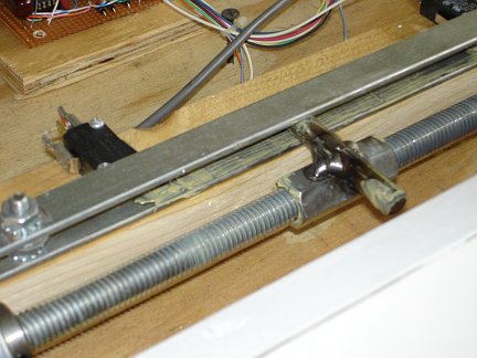
Here is a view of the threaded rod. It is 1/2 inch diameter, 13 threads to the inch. The long nut rides on the rod. This is
a type of nut called a coupling nut. It is ordinarily used for coupling two pieces of threaded rod together. That's why
it's so long. I used a coupling nut here because it wobbles less on the rod than an ordinary nut because it has more threads in
contact with the rod. You can find coupling nuts in just about any hardware or home center store right next to the threaded rod. A steel
pin is welded to the nut. One side of the pin rides between two steel plates which prevent the nut from rotating. The other
end of the pin engages a slot in a tab (visible in the next photo) which sticks down from the underside of the top plate. You can also
see one of the limit switches on the left. Everything is thoroughly greased for smooth operation.
The slotted steel tab and the steel pin welded to the drive nut are the only metal pieces that had to
be custom fabricated. A machinist friend of mine made them for me. Everything else is made from standard hardware and fasteners
available in most well stocked hardware or home center stores.
Here is a view of the underside of the top plate removed from the platform. The two sectors were cut from hard-wood
plywood using my router and a circle cutting jig. Each sector is a different radius corresponding to slices of a tilted
cone. The North sector has a radius of 35 inches and the South sector has a radius of 24 inches. Both are 4 inches tall. Each sector has a 1/8
inch thick band of Aluminum attached to it's outer rim to provide a smooth surface to ride
against the bearings on the base unit. Each sector also has two squares of super slippery GoreTex which rides against
Formica crescents on the base unit reducing friction. You can see the bearings and Formica backing on the North side of the base in
the fourth photo from the top. The inside of the South side of the base is similar.
Here you can also see the slotted steel tab sticking up which engages the drive
pin on the base unit.
This picture was taken by squeezing the camera through the gap between the upper plate and the base unit. It shows how the
slotted tab on the upper plate engages the steel drive pin on the base section. I designed the platform this way to keep
as much of the drive machinery as possible covered up and protected from the elements, dust and grit. I've seen a lot of
platforms that had all the drive hardware stuck on the outside of the unit and exposed to everything Mother Nature and
careless astronomers could throw at it. I do think I made one mistake here though. I now think the pin
should engage the slot at a 90 degree angle. I think that might reduce the amount of torque required to move the platform, reduce
binding at the extremes of travel, and
perhaps allow it to move a little further in either direction. Once summer arrives and the weather goes to hell here in
Florida, I will probably rework the platform so that the pin engages at 90 degrees and see if it really works any better. If
so, I'll have an even better platform ready when the weather dries out, the mosquitos die off, and the nights get long again next fall.
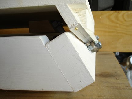
Here is a close-up side view of the North bearings from the side with the top plate in place. The plywood sector with its metal
banding on the rim rides against the sealed ball bearings. Between the plywood sector and the 2X4 base is the GoreTex on Formica
bearing (not visible).
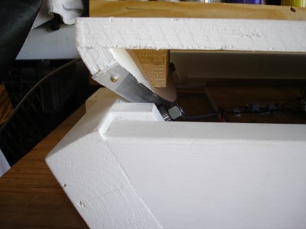
Here is a view of the South bearings from the side with the top plate in place. This is identical to the North side except that the bearings
are mounted inside the base unit.
Here is a view of the south side showing the single South leveling foot. There are two leveling feet on the North side. You only need three
feet since every object only rests on three points. Now you know why all four-legged tables rock. One leg will always be off
the ground. With three legs there is no rocking. Just spread the three points out into the widest possible triangle for the
most stability. When setting up in grass or dirt I place small squares of plywood under each foot to prevent them from sinking into
the soft ground. On a hard surface like concrete or asphalt the plywood isn't needed.
Here is a shot of the underside of the platform showing the three leveling feet. I should also explain why it is painted white. I get
a lot of questions about that for some reason. I wanted to protect all the wooden surfaces that would be subject to having dew condense on them,
have dew running off the telescope drip on them, or be in contact with dewy grass. I chose white paint so that the platform
is as visible as possible in the dark so I don't trip over it or accidentally kick it while working around the telescope. This is not much
of a problem when the 17.5 inch Dob is sitting on the platform since it pretty much completely covers it. However, in my testing of the
platform with smaller scopes, it was a problem. It's also nice to be able to easily see exactly where the platform is when setting up
or tearing down at night without having to turn on a light, thus preserving my precious night vision for hunting down faint galaxies and such.
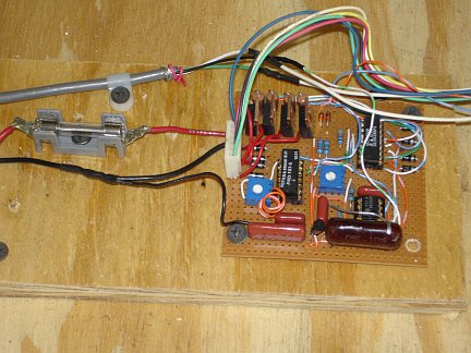
Here is a photo of the electronic circuitry that drives the stepper motor. It is based on the UCN5804B single chip stepper motor driver.
A 555 timer circuit is tuned with a trimpot to provide about 375 pulses per second to the driver chip to move the motor at the sidereal rate.
The motor is a 200 step/rev model that is half stepped. This means I get not quite one revolution per second out of the motor at the
sidereal rate. For resetting the platform, the motor direction is reversed, the step mode is changed from half to full, and a reed relay
cuts a second trimpot into the 555 circuit to speed up the pulse rate. The UCN5804B is supposedly (according to its spec sheet) capable of
driving the motor I am using directly. However, I initially used a much bigger stepper motor in this project. So I added four big driver
transistors to the board and used the outputs of the UCN5804B to switch them. I probably would have done it anyway since I tend to over-engineer
things. Stuff I build never dies. For visual observing the platform works great. For photography though, drift becomes a problem.
In the future I want to add a multi-turn trimpot to the hand controller and wire it in series with the
main timing pot on the circuit board so I can fine-tune the speed of the platform for photography.
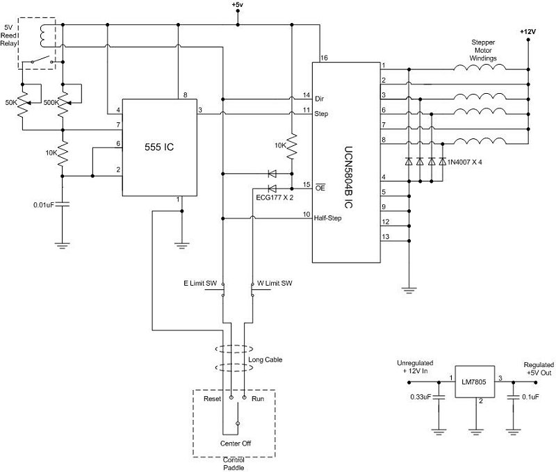
Here is a schematic of the drive circuitry. Sorry it took so long to all who have been clamoring for it. I somehow lost my notes on this project
when I moved some time ago. I couldn't find the schematic I drew up for it. Finally I decided to bite the bullet and reverse-engineer
the thing and recreate the schematic. Click on it for a larger version. I used the UCN5804B stepper motor driver IC by Allegro. Unfortunately, this chip is now
obsolete. I wish I'd bought a boatload of them before they went obsolete. You may be able to still find some NOS out there. This
circuit will drive a small stepper motor as is. To drive a big stepper that needs an Amp or more per phase, you should probably
add some hefty driver transistors. To calibrate the electronics, start by tuning the 500K pot to the speed to give you the sidereal
tracking rate. This will take a lot of fiddling and drift tests. Tune the 50K pot to the highest speed your stepper motor can handle
for resetting the platform without stalling out. Both calibrations should be done with the normal weight load on the platform that
it would see in use. Setting up and tearing down the big DOB for all testing and calibration the platform needed was too much of
a hassle, so I used my "little" 6 inch DOB for drift testing, and piled a lot of scrap iron on the platform to simulate
the weight load of the big scope.
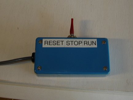
Here is a photo of the hand controller for the platform. It is on a long cable and has Velcro on the back which allows me
to stick it to a convenient spot on the side of the telescope. The controller only has three functions. Run, Stop and Reset.
In the run position the platform rotates from East to West at the sidereal rate counteracting the Earth's rotation. The platform
will run for 40 minutes before needing to be reset. In the reset position the platform will run at high speed from West
back to East. The platform stops on its own at either end of travel. I can also stop it anytime by putting the switch in
the stop position, which I do at times when the telescope doesn't need to be driven so as to minimize the number of reset cycles
during an observing session. A reset cycle takes about ten minutes. The little motor just doesn't have enough torque at
higher speeds to move the mass of the platform with a big telescope on it. It just stalls out if I try to speed up the reset
cycle any more. That's ok though. The ten minute reset cycle gives me a chance to sit down for a while, relax and consult
my star charts and decide which objects to observe next.
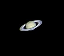
Here's a photo of Saturn taken through the big Dob on the platform, using a ToUcam. Astrophotography with a Dob! What a concept!
With improvements, I hope to do a little deep sky photography with the platform too.
 Here is a photo of the 17.5 inch Dobsonian telescope on my new equatorial platform. Here the scope is set up at the
Orange Blossom Special Star Party at Alafia River State Park in February 2006. It was the first real test of the
platform (outside my back yard). All though I had built it specifically for use with the big Dob, I had not yet
had a chance to actually test it with anything as heavy as the big Dob. It was only finished a few days before the
star party and I had only tested it with one of my much smaller scopes. I was a little worried about whether it would
really work with all that weight sitting on it. If anything it seems to work even better and more smoothly with
the larger load of the big Dob.
Here is a photo of the 17.5 inch Dobsonian telescope on my new equatorial platform. Here the scope is set up at the
Orange Blossom Special Star Party at Alafia River State Park in February 2006. It was the first real test of the
platform (outside my back yard). All though I had built it specifically for use with the big Dob, I had not yet
had a chance to actually test it with anything as heavy as the big Dob. It was only finished a few days before the
star party and I had only tested it with one of my much smaller scopes. I was a little worried about whether it would
really work with all that weight sitting on it. If anything it seems to work even better and more smoothly with
the larger load of the big Dob.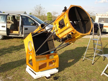 Here's another view of the scope sitting on the equatorial platform. Having an equatorial platform is a big help
when I am at a public observing event and I have a long line of people at the telescope wanting to see the
wonders of the universe. I can put the scope on an object (even at really high power) and just walk away. The
platform will do the work for me. Dozens of people can get a good long look through the scope without my having
to jump in after every person or two and re-aim the telescope as the Earth rotates the object out of interest
out of view. Below are some close-up photos of the platform.
Here's another view of the scope sitting on the equatorial platform. Having an equatorial platform is a big help
when I am at a public observing event and I have a long line of people at the telescope wanting to see the
wonders of the universe. I can put the scope on an object (even at really high power) and just walk away. The
platform will do the work for me. Dozens of people can get a good long look through the scope without my having
to jump in after every person or two and re-aim the telescope as the Earth rotates the object out of interest
out of view. Below are some close-up photos of the platform.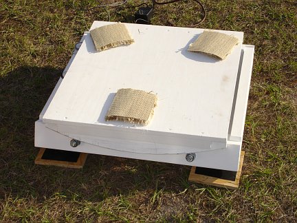 Here is a view of the platform without the telescope sitting on it. The top is 24 inches square. The three pads of
carpet help prevent vibration from the drive motor exciting the telescope. Here it is in the middle of its range of
travel and the top is flat. This is the best position for setting up the telescope on top of it. After the scope is
set up, the platform is reset to it's extreme Easterly position. The platform was built to work at 30 degrees North latitude.
this is a good compromise since I will be using it both in Florida and Arizona. In Florida the North end needs to be
tilted down a couple of degrees. In Arizona it needs to be tilted up a few degrees. There are three levelling feet on the
underside that allow me to level and tilt the platform as needed for a perfect alignment. A small bubble level and a
compass are all the tools I need for alignment.
Here is a view of the platform without the telescope sitting on it. The top is 24 inches square. The three pads of
carpet help prevent vibration from the drive motor exciting the telescope. Here it is in the middle of its range of
travel and the top is flat. This is the best position for setting up the telescope on top of it. After the scope is
set up, the platform is reset to it's extreme Easterly position. The platform was built to work at 30 degrees North latitude.
this is a good compromise since I will be using it both in Florida and Arizona. In Florida the North end needs to be
tilted down a couple of degrees. In Arizona it needs to be tilted up a few degrees. There are three levelling feet on the
underside that allow me to level and tilt the platform as needed for a perfect alignment. A small bubble level and a
compass are all the tools I need for alignment.
 Here is an overview of the equatorial platform as seen from the North side with the top plate removed. I'll go into some
of the details about how it works below. Here is an
overview. A stepper motor turns a worm gear which turns a piece of half inch threaded rod. There is a nut with a steel
pin welded to it that travels left to right on the threaded rod as it rotates. The pin engages a slotted tab on the underside
of the top plate and drags it along. The top plate sits on sectors which ride on tilted bearings which point through
the North Celestial Pole. The platform will run for 40 minutes before the pin on the nut hits the West limit switch and
shuts the motor down. Another limit switch on the East side shuts the motor down at the end of a reset cycle.
Here is an overview of the equatorial platform as seen from the North side with the top plate removed. I'll go into some
of the details about how it works below. Here is an
overview. A stepper motor turns a worm gear which turns a piece of half inch threaded rod. There is a nut with a steel
pin welded to it that travels left to right on the threaded rod as it rotates. The pin engages a slotted tab on the underside
of the top plate and drags it along. The top plate sits on sectors which ride on tilted bearings which point through
the North Celestial Pole. The platform will run for 40 minutes before the pin on the nut hits the West limit switch and
shuts the motor down. Another limit switch on the East side shuts the motor down at the end of a reset cycle.
 Here is another overview of the platform from the side with the top plate removed. The North side is on the left and the South
side is on the right. As you can see, the North and South sides are tilted up at 30 degrees. The bearings on the South side
are inside the base. The bearings on the North side are on the outside of the base. The frame of the base unit is made from
2X4s. The 2X4s are screwed together with long wood screws. The corners are reinforced with wood glue blocks. A plywood panel
screwed onto the bottom provides a platform for the drive system and further reinforces the frame by preventing it from skewing
out of square. The bearings are 1 inch
diameter sealed ball bearing units with 1/2 inch bores. They are mounted on 1/2 inch carriage bolts which pass through the
2X4 frame on the North and South sides. Formica crescents are glued on the North and South faces between the ball bearings.
GoreTex pads on the backs of the plywood sectors of the top plate ride against the Formica creating another bearing surface.
Here is another overview of the platform from the side with the top plate removed. The North side is on the left and the South
side is on the right. As you can see, the North and South sides are tilted up at 30 degrees. The bearings on the South side
are inside the base. The bearings on the North side are on the outside of the base. The frame of the base unit is made from
2X4s. The 2X4s are screwed together with long wood screws. The corners are reinforced with wood glue blocks. A plywood panel
screwed onto the bottom provides a platform for the drive system and further reinforces the frame by preventing it from skewing
out of square. The bearings are 1 inch
diameter sealed ball bearing units with 1/2 inch bores. They are mounted on 1/2 inch carriage bolts which pass through the
2X4 frame on the North and South sides. Formica crescents are glued on the North and South faces between the ball bearings.
GoreTex pads on the backs of the plywood sectors of the top plate ride against the Formica creating another bearing surface.
 Here's a close-up of the drive motor and gearing. A 200 step/rev stepper motor salvaged from an old disk drive is half-stepped at
375 steps per second. Half stepping reduces vibration. The motor is mounted on rubber pads to further damp out vibration. The
motor turns a 30:1 ratio worm gear, which is attached to the end of the main threaded drive rod. Everything about this layout is
about reducing and damping out vibration from the motor. The half stepping and the 30:1 ratio mean that the motor must be stepped
very fast. Fast steps mean a high frequency vibration that damps out much more easily than slower clunk-clunk-clunk type steps if the
motor were coupled directly to the threaded rod. The 30:1 gear ratio also means that a much smaller motor can be used to drive the
platform. A smaller motor means - you guessed it - less vibration. If I had it to do over I'd probably try to use something other
than a stepper motor to drive it. It's just so much easier to make stepper motors move at an arbitrary rate of speed as compared to
the alternatives like servos and ac motors. I didn't have the time to get elaborate with the drive electronics, and I have a lot
of experience with steppers, so that's the rout I took. The down side is getting rid of the vibration from the stepper motor. It
took a little trial and error, but in the end I managed to totally eliminate the vibration at the telescope eyepiece.
Here's a close-up of the drive motor and gearing. A 200 step/rev stepper motor salvaged from an old disk drive is half-stepped at
375 steps per second. Half stepping reduces vibration. The motor is mounted on rubber pads to further damp out vibration. The
motor turns a 30:1 ratio worm gear, which is attached to the end of the main threaded drive rod. Everything about this layout is
about reducing and damping out vibration from the motor. The half stepping and the 30:1 ratio mean that the motor must be stepped
very fast. Fast steps mean a high frequency vibration that damps out much more easily than slower clunk-clunk-clunk type steps if the
motor were coupled directly to the threaded rod. The 30:1 gear ratio also means that a much smaller motor can be used to drive the
platform. A smaller motor means - you guessed it - less vibration. If I had it to do over I'd probably try to use something other
than a stepper motor to drive it. It's just so much easier to make stepper motors move at an arbitrary rate of speed as compared to
the alternatives like servos and ac motors. I didn't have the time to get elaborate with the drive electronics, and I have a lot
of experience with steppers, so that's the rout I took. The down side is getting rid of the vibration from the stepper motor. It
took a little trial and error, but in the end I managed to totally eliminate the vibration at the telescope eyepiece.
 Here is a view of the threaded rod. It is 1/2 inch diameter, 13 threads to the inch. The long nut rides on the rod. This is
a type of nut called a coupling nut. It is ordinarily used for coupling two pieces of threaded rod together. That's why
it's so long. I used a coupling nut here because it wobbles less on the rod than an ordinary nut because it has more threads in
contact with the rod. You can find coupling nuts in just about any hardware or home center store right next to the threaded rod. A steel
pin is welded to the nut. One side of the pin rides between two steel plates which prevent the nut from rotating. The other
end of the pin engages a slot in a tab (visible in the next photo) which sticks down from the underside of the top plate. You can also
see one of the limit switches on the left. Everything is thoroughly greased for smooth operation.
The slotted steel tab and the steel pin welded to the drive nut are the only metal pieces that had to
be custom fabricated. A machinist friend of mine made them for me. Everything else is made from standard hardware and fasteners
available in most well stocked hardware or home center stores.
Here is a view of the threaded rod. It is 1/2 inch diameter, 13 threads to the inch. The long nut rides on the rod. This is
a type of nut called a coupling nut. It is ordinarily used for coupling two pieces of threaded rod together. That's why
it's so long. I used a coupling nut here because it wobbles less on the rod than an ordinary nut because it has more threads in
contact with the rod. You can find coupling nuts in just about any hardware or home center store right next to the threaded rod. A steel
pin is welded to the nut. One side of the pin rides between two steel plates which prevent the nut from rotating. The other
end of the pin engages a slot in a tab (visible in the next photo) which sticks down from the underside of the top plate. You can also
see one of the limit switches on the left. Everything is thoroughly greased for smooth operation.
The slotted steel tab and the steel pin welded to the drive nut are the only metal pieces that had to
be custom fabricated. A machinist friend of mine made them for me. Everything else is made from standard hardware and fasteners
available in most well stocked hardware or home center stores.
 Here is a view of the underside of the top plate removed from the platform. The two sectors were cut from hard-wood
plywood using my router and a circle cutting jig. Each sector is a different radius corresponding to slices of a tilted
cone. The North sector has a radius of 35 inches and the South sector has a radius of 24 inches. Both are 4 inches tall. Each sector has a 1/8
inch thick band of Aluminum attached to it's outer rim to provide a smooth surface to ride
against the bearings on the base unit. Each sector also has two squares of super slippery GoreTex which rides against
Formica crescents on the base unit reducing friction. You can see the bearings and Formica backing on the North side of the base in
the fourth photo from the top. The inside of the South side of the base is similar.
Here you can also see the slotted steel tab sticking up which engages the drive
pin on the base unit.
Here is a view of the underside of the top plate removed from the platform. The two sectors were cut from hard-wood
plywood using my router and a circle cutting jig. Each sector is a different radius corresponding to slices of a tilted
cone. The North sector has a radius of 35 inches and the South sector has a radius of 24 inches. Both are 4 inches tall. Each sector has a 1/8
inch thick band of Aluminum attached to it's outer rim to provide a smooth surface to ride
against the bearings on the base unit. Each sector also has two squares of super slippery GoreTex which rides against
Formica crescents on the base unit reducing friction. You can see the bearings and Formica backing on the North side of the base in
the fourth photo from the top. The inside of the South side of the base is similar.
Here you can also see the slotted steel tab sticking up which engages the drive
pin on the base unit.
 This picture was taken by squeezing the camera through the gap between the upper plate and the base unit. It shows how the
slotted tab on the upper plate engages the steel drive pin on the base section. I designed the platform this way to keep
as much of the drive machinery as possible covered up and protected from the elements, dust and grit. I've seen a lot of
platforms that had all the drive hardware stuck on the outside of the unit and exposed to everything Mother Nature and
careless astronomers could throw at it. I do think I made one mistake here though. I now think the pin
should engage the slot at a 90 degree angle. I think that might reduce the amount of torque required to move the platform, reduce
binding at the extremes of travel, and
perhaps allow it to move a little further in either direction. Once summer arrives and the weather goes to hell here in
Florida, I will probably rework the platform so that the pin engages at 90 degrees and see if it really works any better. If
so, I'll have an even better platform ready when the weather dries out, the mosquitos die off, and the nights get long again next fall.
This picture was taken by squeezing the camera through the gap between the upper plate and the base unit. It shows how the
slotted tab on the upper plate engages the steel drive pin on the base section. I designed the platform this way to keep
as much of the drive machinery as possible covered up and protected from the elements, dust and grit. I've seen a lot of
platforms that had all the drive hardware stuck on the outside of the unit and exposed to everything Mother Nature and
careless astronomers could throw at it. I do think I made one mistake here though. I now think the pin
should engage the slot at a 90 degree angle. I think that might reduce the amount of torque required to move the platform, reduce
binding at the extremes of travel, and
perhaps allow it to move a little further in either direction. Once summer arrives and the weather goes to hell here in
Florida, I will probably rework the platform so that the pin engages at 90 degrees and see if it really works any better. If
so, I'll have an even better platform ready when the weather dries out, the mosquitos die off, and the nights get long again next fall.
 Here is a close-up side view of the North bearings from the side with the top plate in place. The plywood sector with its metal
banding on the rim rides against the sealed ball bearings. Between the plywood sector and the 2X4 base is the GoreTex on Formica
bearing (not visible).
Here is a close-up side view of the North bearings from the side with the top plate in place. The plywood sector with its metal
banding on the rim rides against the sealed ball bearings. Between the plywood sector and the 2X4 base is the GoreTex on Formica
bearing (not visible).
 Here is a view of the South bearings from the side with the top plate in place. This is identical to the North side except that the bearings
are mounted inside the base unit.
Here is a view of the South bearings from the side with the top plate in place. This is identical to the North side except that the bearings
are mounted inside the base unit.
 Here is a view of the south side showing the single South leveling foot. There are two leveling feet on the North side. You only need three
feet since every object only rests on three points. Now you know why all four-legged tables rock. One leg will always be off
the ground. With three legs there is no rocking. Just spread the three points out into the widest possible triangle for the
most stability. When setting up in grass or dirt I place small squares of plywood under each foot to prevent them from sinking into
the soft ground. On a hard surface like concrete or asphalt the plywood isn't needed.
Here is a view of the south side showing the single South leveling foot. There are two leveling feet on the North side. You only need three
feet since every object only rests on three points. Now you know why all four-legged tables rock. One leg will always be off
the ground. With three legs there is no rocking. Just spread the three points out into the widest possible triangle for the
most stability. When setting up in grass or dirt I place small squares of plywood under each foot to prevent them from sinking into
the soft ground. On a hard surface like concrete or asphalt the plywood isn't needed.
 Here is a shot of the underside of the platform showing the three leveling feet. I should also explain why it is painted white. I get
a lot of questions about that for some reason. I wanted to protect all the wooden surfaces that would be subject to having dew condense on them,
have dew running off the telescope drip on them, or be in contact with dewy grass. I chose white paint so that the platform
is as visible as possible in the dark so I don't trip over it or accidentally kick it while working around the telescope. This is not much
of a problem when the 17.5 inch Dob is sitting on the platform since it pretty much completely covers it. However, in my testing of the
platform with smaller scopes, it was a problem. It's also nice to be able to easily see exactly where the platform is when setting up
or tearing down at night without having to turn on a light, thus preserving my precious night vision for hunting down faint galaxies and such.
Here is a shot of the underside of the platform showing the three leveling feet. I should also explain why it is painted white. I get
a lot of questions about that for some reason. I wanted to protect all the wooden surfaces that would be subject to having dew condense on them,
have dew running off the telescope drip on them, or be in contact with dewy grass. I chose white paint so that the platform
is as visible as possible in the dark so I don't trip over it or accidentally kick it while working around the telescope. This is not much
of a problem when the 17.5 inch Dob is sitting on the platform since it pretty much completely covers it. However, in my testing of the
platform with smaller scopes, it was a problem. It's also nice to be able to easily see exactly where the platform is when setting up
or tearing down at night without having to turn on a light, thus preserving my precious night vision for hunting down faint galaxies and such.
 Here is a photo of the electronic circuitry that drives the stepper motor. It is based on the UCN5804B single chip stepper motor driver.
A 555 timer circuit is tuned with a trimpot to provide about 375 pulses per second to the driver chip to move the motor at the sidereal rate.
The motor is a 200 step/rev model that is half stepped. This means I get not quite one revolution per second out of the motor at the
sidereal rate. For resetting the platform, the motor direction is reversed, the step mode is changed from half to full, and a reed relay
cuts a second trimpot into the 555 circuit to speed up the pulse rate. The UCN5804B is supposedly (according to its spec sheet) capable of
driving the motor I am using directly. However, I initially used a much bigger stepper motor in this project. So I added four big driver
transistors to the board and used the outputs of the UCN5804B to switch them. I probably would have done it anyway since I tend to over-engineer
things. Stuff I build never dies. For visual observing the platform works great. For photography though, drift becomes a problem.
In the future I want to add a multi-turn trimpot to the hand controller and wire it in series with the
main timing pot on the circuit board so I can fine-tune the speed of the platform for photography.
Here is a photo of the electronic circuitry that drives the stepper motor. It is based on the UCN5804B single chip stepper motor driver.
A 555 timer circuit is tuned with a trimpot to provide about 375 pulses per second to the driver chip to move the motor at the sidereal rate.
The motor is a 200 step/rev model that is half stepped. This means I get not quite one revolution per second out of the motor at the
sidereal rate. For resetting the platform, the motor direction is reversed, the step mode is changed from half to full, and a reed relay
cuts a second trimpot into the 555 circuit to speed up the pulse rate. The UCN5804B is supposedly (according to its spec sheet) capable of
driving the motor I am using directly. However, I initially used a much bigger stepper motor in this project. So I added four big driver
transistors to the board and used the outputs of the UCN5804B to switch them. I probably would have done it anyway since I tend to over-engineer
things. Stuff I build never dies. For visual observing the platform works great. For photography though, drift becomes a problem.
In the future I want to add a multi-turn trimpot to the hand controller and wire it in series with the
main timing pot on the circuit board so I can fine-tune the speed of the platform for photography.
 Here is a photo of the hand controller for the platform. It is on a long cable and has Velcro on the back which allows me
to stick it to a convenient spot on the side of the telescope. The controller only has three functions. Run, Stop and Reset.
In the run position the platform rotates from East to West at the sidereal rate counteracting the Earth's rotation. The platform
will run for 40 minutes before needing to be reset. In the reset position the platform will run at high speed from West
back to East. The platform stops on its own at either end of travel. I can also stop it anytime by putting the switch in
the stop position, which I do at times when the telescope doesn't need to be driven so as to minimize the number of reset cycles
during an observing session. A reset cycle takes about ten minutes. The little motor just doesn't have enough torque at
higher speeds to move the mass of the platform with a big telescope on it. It just stalls out if I try to speed up the reset
cycle any more. That's ok though. The ten minute reset cycle gives me a chance to sit down for a while, relax and consult
my star charts and decide which objects to observe next.
Here is a photo of the hand controller for the platform. It is on a long cable and has Velcro on the back which allows me
to stick it to a convenient spot on the side of the telescope. The controller only has three functions. Run, Stop and Reset.
In the run position the platform rotates from East to West at the sidereal rate counteracting the Earth's rotation. The platform
will run for 40 minutes before needing to be reset. In the reset position the platform will run at high speed from West
back to East. The platform stops on its own at either end of travel. I can also stop it anytime by putting the switch in
the stop position, which I do at times when the telescope doesn't need to be driven so as to minimize the number of reset cycles
during an observing session. A reset cycle takes about ten minutes. The little motor just doesn't have enough torque at
higher speeds to move the mass of the platform with a big telescope on it. It just stalls out if I try to speed up the reset
cycle any more. That's ok though. The ten minute reset cycle gives me a chance to sit down for a while, relax and consult
my star charts and decide which objects to observe next.
 Here's a photo of Saturn taken through the big Dob on the platform, using a ToUcam. Astrophotography with a Dob! What a concept!
With improvements, I hope to do a little deep sky photography with the platform too.
Here's a photo of Saturn taken through the big Dob on the platform, using a ToUcam. Astrophotography with a Dob! What a concept!
With improvements, I hope to do a little deep sky photography with the platform too.