Click on the photos for larger versions. |
The Cookie Jar is the more unique creations to come out of my telescope workshop.
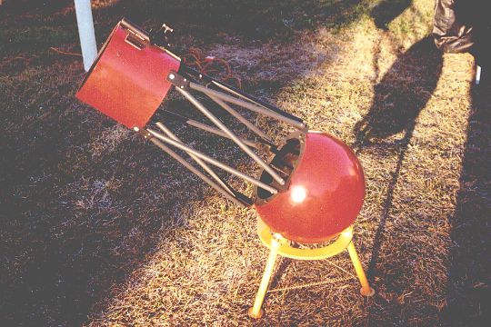
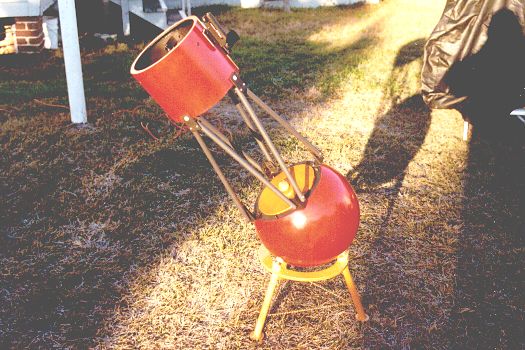
It is an 8 inch f/4.5 Newtonian telescope on a ball mounting. It was designed to give bright wide field views of the night sky, while still having excellent high power planetary performance. The two piece design means setup/breakdown time is nil. I custom designed and built this scope for my good friend Andy Hradesky. Andy wanted something unique, and gave me free rein to let my creativity run amok. The result has been described as the bastard offspring of an Edmund Astroscan, and a Portaball scope. I had some trouble naming this scope. My friends suggested many names, including the rather unflattering "flatuscope" because of the wonderful "farty" noises it makes when the felt pads on the base get wet with dew. Eventually, Andy's girlfriend Barbie Jo dubbed it the "cookie jar" after seeing it with the dust cap in place. The name stuck. I liked the Cookie Jar so much that I built one for myself too. The Cookie Jar telescope has a low to the ground "kid friendly" design. It's ball mounting gives it an infinitely adjustable eyepiece position. This makes it great for use with both kids and adults without the need to carry around a ladder. I use this scope at public observing sessions and when I am teaching astronomy. The ball mounting also doesn't suffer from the "Dob Hole" problem that alt-az mounted scopes have near the zenith. The simple two piece design very easy to set up and break down. It is also small enough to transport and store without having to disassemble the optical assembly. The wide spread feet of the base and the very low center of gravity of the ball mounting make for a very stable telescope. Vibration damps out almost immediately. The ball mounting allows an unusual freedom and ease of movement. The scope has complete freedom of motion in altitude, azimuth and rotation meaning that no contortions are necessary to reach the eyepiece no matter where in the sky the telescope is pointed. The Cookie Jar is a truly unique telescope. It really stands out of the crowd at star parties. |
Specifications of the Cookie Jar telescope
| Primary Mirror: | 8 inch f/4.5 |
| Secondary Mirror: | 1.75in. |
| Mirror Manufacturer: | Murnaghan Instruments |
| Focal Length: | 36in. / 914mm |
| Primary Cell: | Custom with Remote Collimation |
| Secondary Holder: | Custom Fully Adjustable |
| Spider: | Custom 3 Vane Curved |
| Focuser: | 1.25in. Low-profile, Helical |
| Finder: | Orion EZ Finder Reflex Sight |
| Eyepiece Height At Zenith: | 39.5in. |
| Overall Length: | 44in. |
| Weight: | Approx. 30 lbs |
Photos of the construction of the Cookie Jar
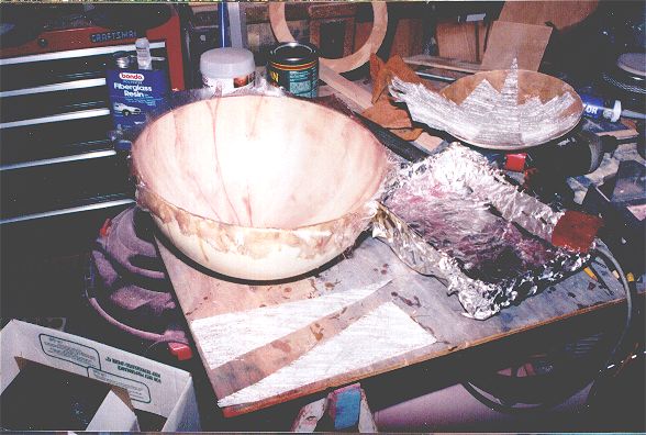 This photo shows the process of laying up the fiberglass for half of a sphere. The mold is an old plastic lamp shade 14.4 in. in diameter. The white wedges are "gores" cut from fiberglass cloth about to be soaked in resin in the foil lined pan then placed in the mold. |
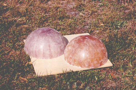 Here are two completed and cured half spheres after being popped out of the mold and having excess material trimmed away. |
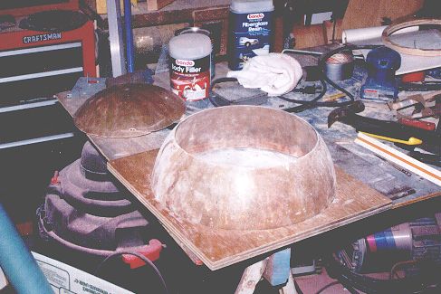 Here one half sphere has been truncated. This creates the opening in the sphere. |
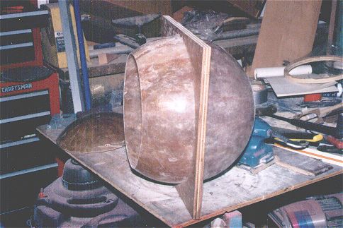 Here a truncated and un truncated hemisphere are being joined together to make the complete sphere for the ball mounting. More fiberglass is used to join the two halves. |
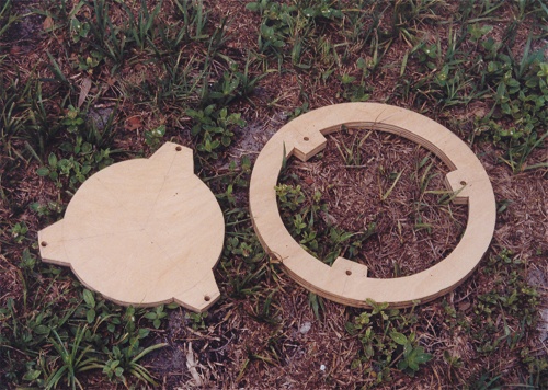 This photo shows the primary mirror cell (left) and the support ring it will hang from (right) once installed inside the sphere. Both parts are made out of hardwood plywood. The primary mirror will sit on felt pads on the piece on the left. Clips will hold it in place. |
 This photo shows how the "ears" and bolt holes line up on the two parts. When installed in the sphere the mirror cell (shown on top here) would hang below the support ring and the two pieces would be separated by stiff springs. Collimation screws will run through the bolt holes. By rotating the mirror cell so that the "ears" don't overlap, the cell can pass through the center of the ring to insert and remove the primary mirror. |
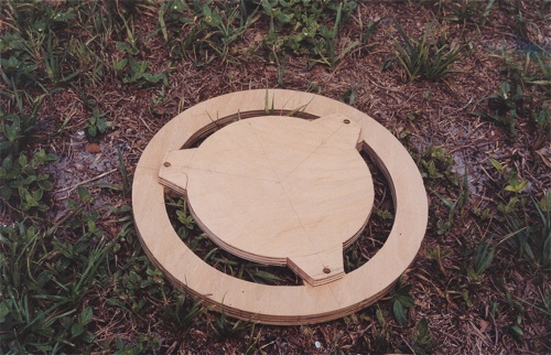
 This photo shows how the support ring and primary mirror cell will sit inside the sphere. |
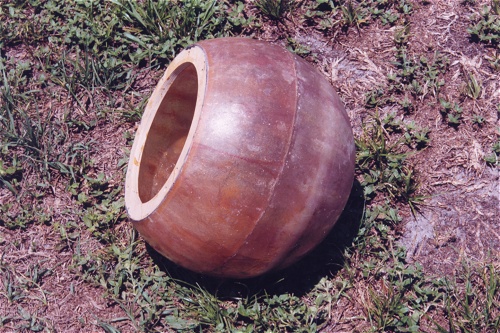
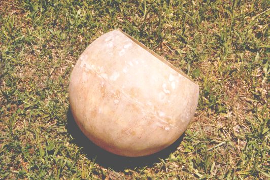 Here is a completed sphere. The blemishes and the line where the two halves join have been touched up with Bondo and the whole thing sanded smooth. |
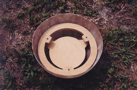
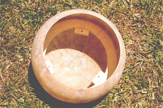 Here is a view inside the sphere showing the wooden support ring that serves as the mounting for the primary mirror cell. The ring has been epoxied to the sphere. Another ring will be epoxied in the opening of the sphere to strengthen it and provide mounting points for the trusses. |
 Here we see the sphere after the second plywood support ring has been epoxied into place in the hole left by truncating the sphere. This ring greatly strengthens the fiberglass sphere and makes it very rigid. It also serves as the mounting point for the lower ends of the trusses. |
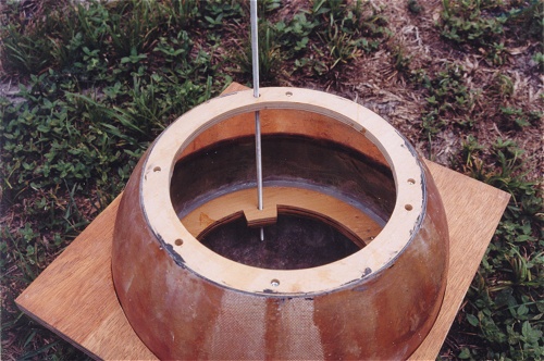 This photo shows how long pieces of threaded rod are used as collimation bolts. They pass through the top support ring, the mirror cell support ring and all the way down to the primary mirror cell (not in place in this photo). This allows for easy collimation of the primary mirror from the top of the sphere. |
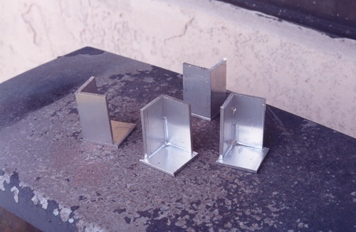 This photo shows the lower truss anchors. They are made by welding a piece of Aluminum angle onto a piece of flat Aluminum stock. This photo was taken before the mounting holes were drilled in them. See the photos below to see how these anchors are used to hold the lower ends of the trusses in place. |
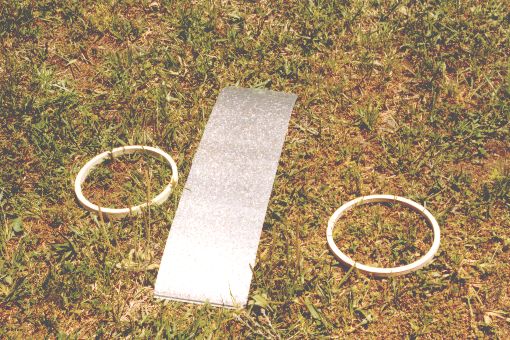 Here are the three parts that make up the secondary cage. The metal band is an 8 inch wide section cut out of a 10 inch diameter piece of steel air conditioning duct. The two rings are cut out of 1/4 inch plywood. |
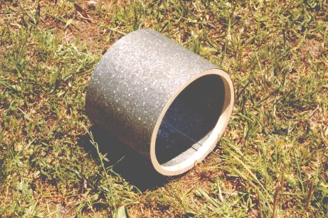 Here is the secondary cage assembled. The steel band has a seam that locks it together. Once the rings are installed and glued in place it makes a rigid but very light secondary cage. Bondo is used to fill the seam in the metal before painting. |
 This photo gives you some idea how the truss assembly is put together. The trusses are aluminum tubes covered with black heat-shrink tubing. |
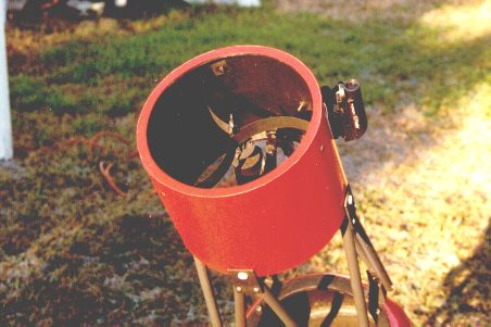
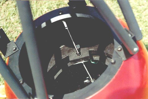 Here you are seeing a peek inside the ball. You can see one of the three collimation screws that come all the way to the top of the ball (since there would be no way to access them from behind like in an ordinary scope). You can also see the reflection of the screw in the primary mirror. |
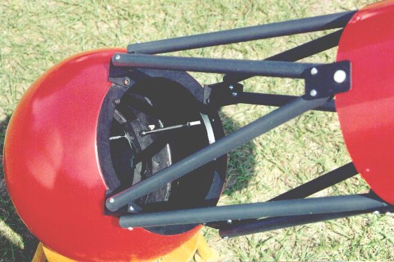
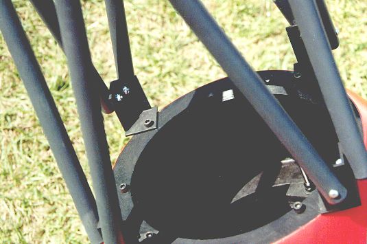 Here you can get some idea of how the trusses are attached to the top ring in the fiberglass ball. |
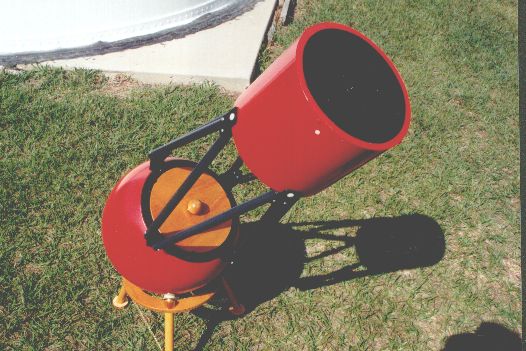 This photo shows the scope with the wooden dust cap in place on the ball. This is how the scope got its name. It looks like a cookie jar. |
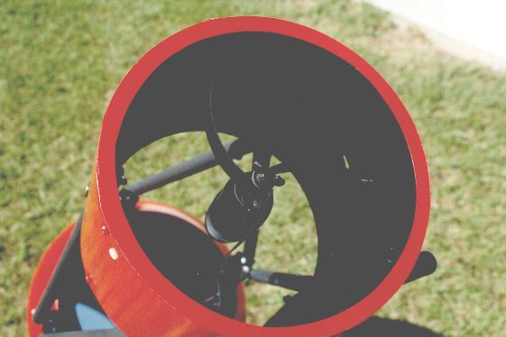 Here is a view of the secondary cage and secondary mirror holder. The three curved vane spider is barely visible in this photo. |
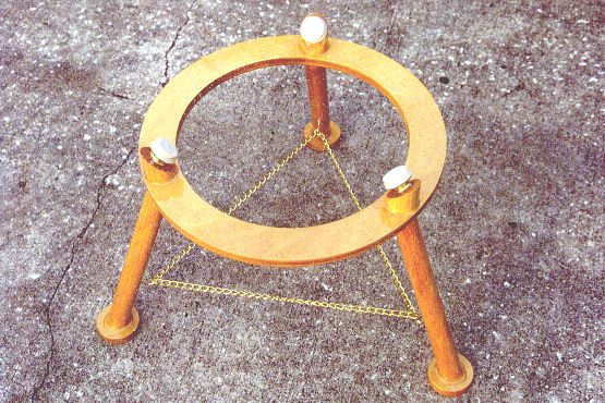
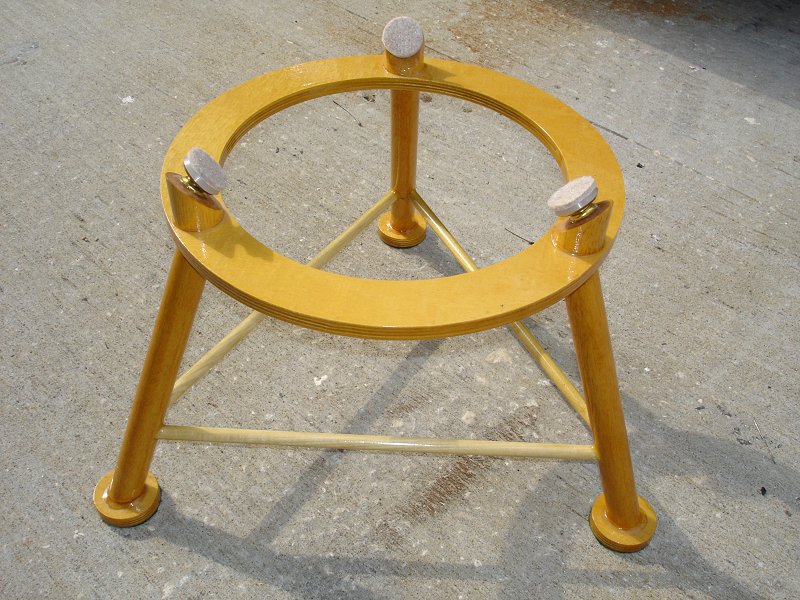 Here is a view of the new and improved base for the telescope. The chains did a pretty good job of preventing the legs from splaying out, but a strong bump from the side could cause them to bend in and break. After that happened a couple of times I replaced the chains with dowels. |