|
I decided I needed a better and more accurate CNC router than my old "Woodpile CNC" machine. I planned on making it (almost) entirely from metal, and mostly using 80/20 components.
80/20 is billed as the industrial "Erector Set", because you can build almost anything from the standardized parts just by bolting them together. I lucked into a bunch of 80/20
stuff cheap a while back, and decided now was the time to build something useful out of it. I really love working with 80/20. It makes everything so easy. Their motto that they've done
80 percent of the work for you, and you just need to supply the last 20 percent is really true. Just about anyone with a few tools and some mechanical and electrical know-how
could build a machine like this. I hope this web page helps inspire others to build their own machines. This video shows most of the steps in the construction of the machine. It is about 47 minutes long. This web page is a companion to the video and goes into more detail about the construction that didn't make it into the video. It also clarifies things that may not have obvious or easily understandable in the video. Just about anyone with a few tools and some mechanical and electrical know-how could build a machine like this. I hope this web page helps inspire others to build their own machines. Click on any of the photos below to see a larger version. |
 So, what exactly is 80/20? It is an aluminum t-slot structural framing system, but it is also so much more than that. It is like an industrial
version of the sort of Erector Sets a lot of us
played with when we were kids. But instead of just building models of machines, you can build the actual machines, or even whole production lines or factories out of this stuff. We had a lot
of custom built equipment made from 80/20 on our production lines in the factories where I have worked. That's where I became familiar with it and how to build things with it.
So, what exactly is 80/20? It is an aluminum t-slot structural framing system, but it is also so much more than that. It is like an industrial
version of the sort of Erector Sets a lot of us
played with when we were kids. But instead of just building models of machines, you can build the actual machines, or even whole production lines or factories out of this stuff. We had a lot
of custom built equipment made from 80/20 on our production lines in the factories where I have worked. That's where I became familiar with it and how to build things with it.
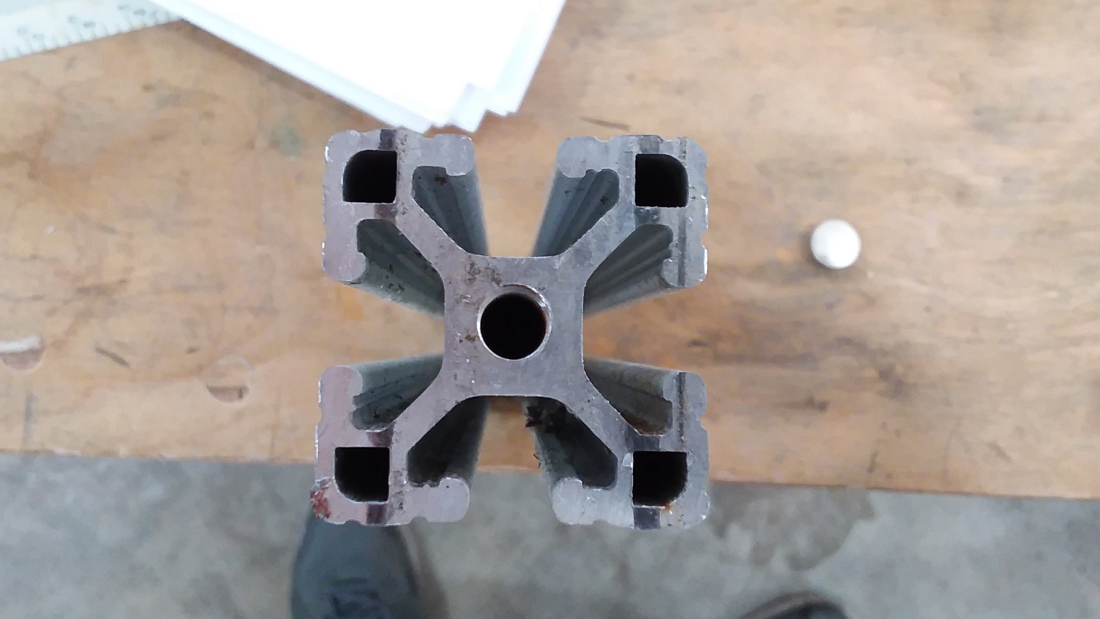
This photo shows a cross-section of a typical piece of 80/20 structural t-slot rail. This particular piece is 1.5 inches square. This is only one out of dozens of sizes and styles of rail.
There is a rail type for any imaginable application, and they are available in any desired length and with a variety of finishes. But the rails are only the beginning. There are all kinds
of fasteners and accessories available that allow you to bolt the rails together in any imaginable configuration, and bolt nearly anything else to the rails. There are also hinges and slides
and all kinds of bits and pieces to allow for both rotary and linear motion. The possibilities are nearly endless. This CNC router build is actually a fairly simple use of the 80/20 system.
I'm basically just using it as the framework to mount other things onto.
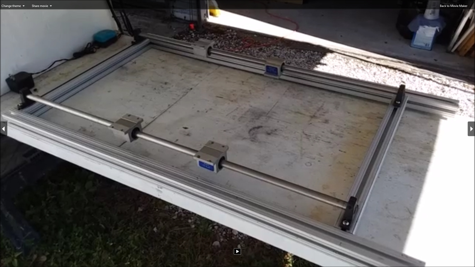 Here I have begun the construction of the machine by creating a framework for the bottom of the machine which everything else will bolt onto. The framework is 40 inches long by 24
inches wide. I then bolted the linear rails and linear bearings for the x axis to the framework. The x rails are 36 inches long. The extra rail length to the right will be used for mounting the
x axis motor. The 80/20 rails bolt together quite easily. They can be custom ordered pre-cut to any length you may need. In my case I cut a lot of my pieces to length myself with a power
miter saw. Then it is just a matter of doing a bit of drilling and tapping to use the special 80/20 fasteners to invisibly bolt the rails together.
Here I have begun the construction of the machine by creating a framework for the bottom of the machine which everything else will bolt onto. The framework is 40 inches long by 24
inches wide. I then bolted the linear rails and linear bearings for the x axis to the framework. The x rails are 36 inches long. The extra rail length to the right will be used for mounting the
x axis motor. The 80/20 rails bolt together quite easily. They can be custom ordered pre-cut to any length you may need. In my case I cut a lot of my pieces to length myself with a power
miter saw. Then it is just a matter of doing a bit of drilling and tapping to use the special 80/20 fasteners to invisibly bolt the rails together.
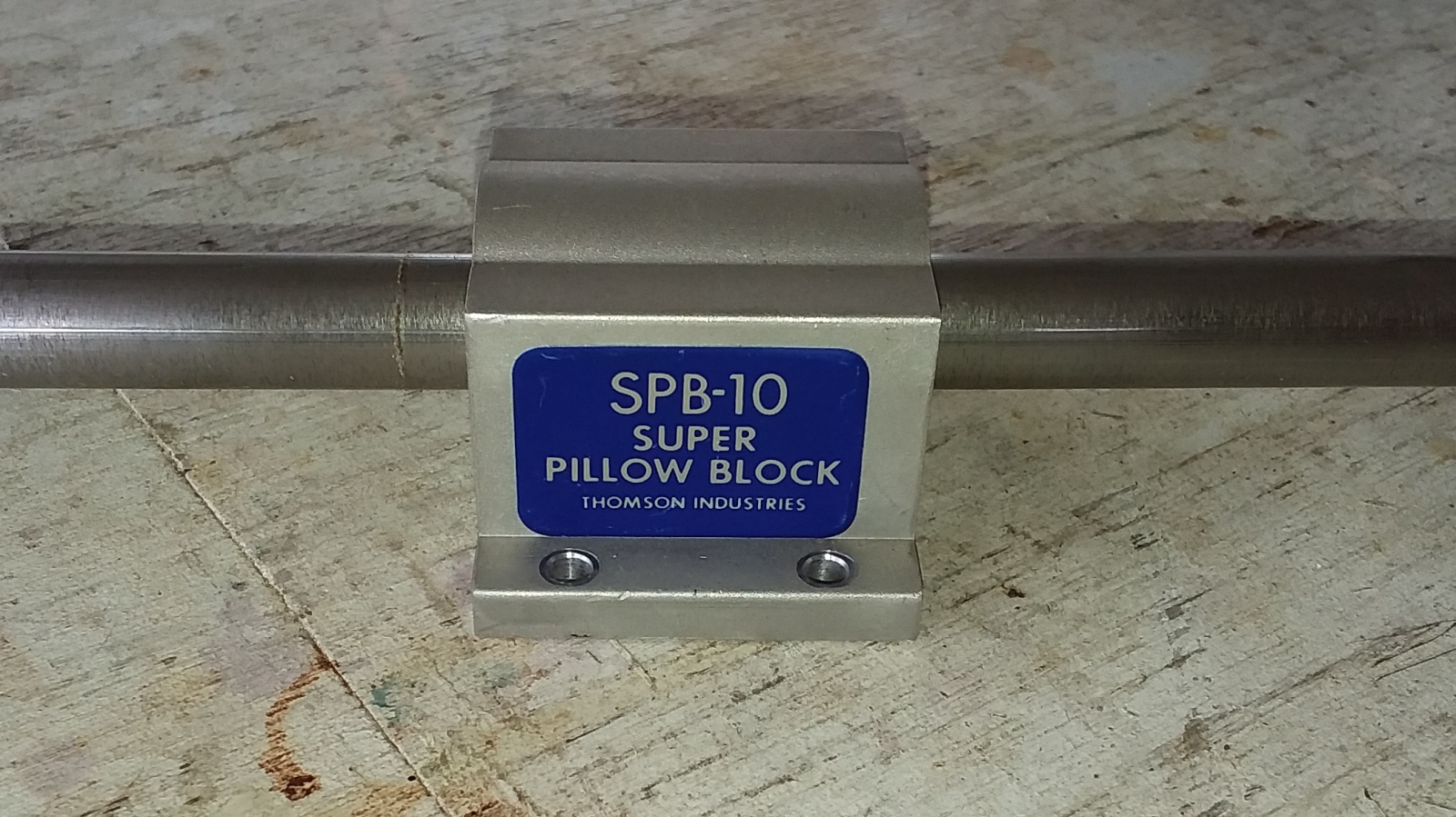 Here is a closeup of one of the linear pillow block bearings I used on both the x and y axes. They are SPB-10 bearings by Thomson. These particular bearings ride on 5/8 inch diameter round
rails. I happened to have a lot of these bearings and several lengths of rail on hand before starting this build. I collect any and all linear motion components I come across at industrial
auctions or going out business sales. That strange compulsion of mine cam in handy during this build. I only had to buy a few things especially for this project to finish it.
Parts like this are expensive new, but can often be had for a song if you are in the right place at the right time. Ebay is also a good place to find
used or NOS (New Old Stock) items like this at very reasonable prices. Rails in any diameter and length can also be found on Ebay or Amazon.
Here is a closeup of one of the linear pillow block bearings I used on both the x and y axes. They are SPB-10 bearings by Thomson. These particular bearings ride on 5/8 inch diameter round
rails. I happened to have a lot of these bearings and several lengths of rail on hand before starting this build. I collect any and all linear motion components I come across at industrial
auctions or going out business sales. That strange compulsion of mine cam in handy during this build. I only had to buy a few things especially for this project to finish it.
Parts like this are expensive new, but can often be had for a song if you are in the right place at the right time. Ebay is also a good place to find
used or NOS (New Old Stock) items like this at very reasonable prices. Rails in any diameter and length can also be found on Ebay or Amazon.

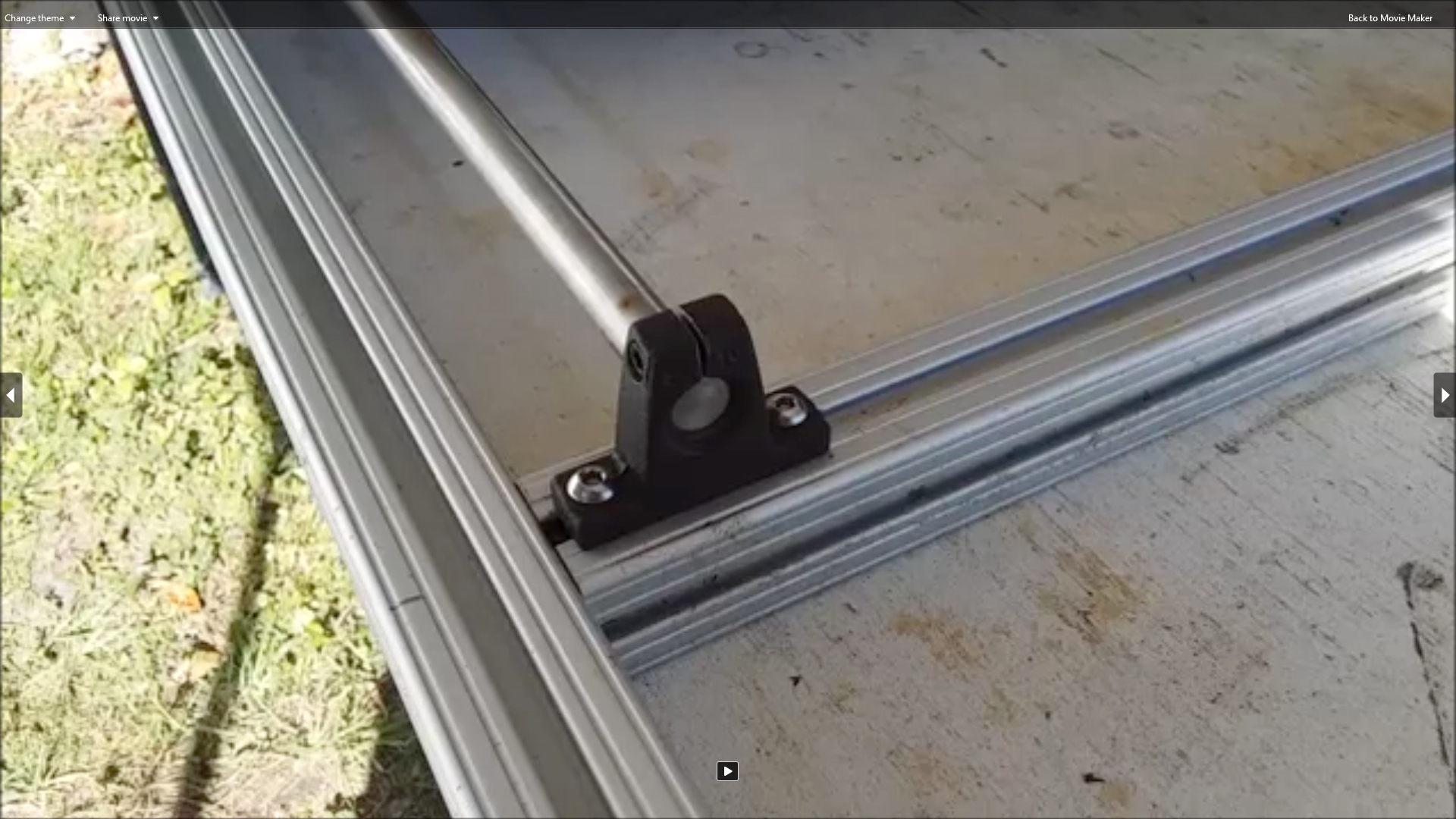 Here is a close-up of one of the Thomson SB-10 rail blocks that anchor the 5/8 inch linear rails at either end. I already had some of these in my parts collection. I found some more on Ebay cheap.
They can be quite expensive if bought new from Thomson. They can be found much cheaper on Ebay from time to time. The mounting holes on the base aren't large
enough to accomodate the 1/4-20 bolts and t-nuts I wanted to use to secure them to the 80/20 rails. Fortunately they are made of soft cast iron and it was easy to drill them out to a larger
size on my drill press.
Here is a close-up of one of the Thomson SB-10 rail blocks that anchor the 5/8 inch linear rails at either end. I already had some of these in my parts collection. I found some more on Ebay cheap.
They can be quite expensive if bought new from Thomson. They can be found much cheaper on Ebay from time to time. The mounting holes on the base aren't large
enough to accomodate the 1/4-20 bolts and t-nuts I wanted to use to secure them to the 80/20 rails. Fortunately they are made of soft cast iron and it was easy to drill them out to a larger
size on my drill press.
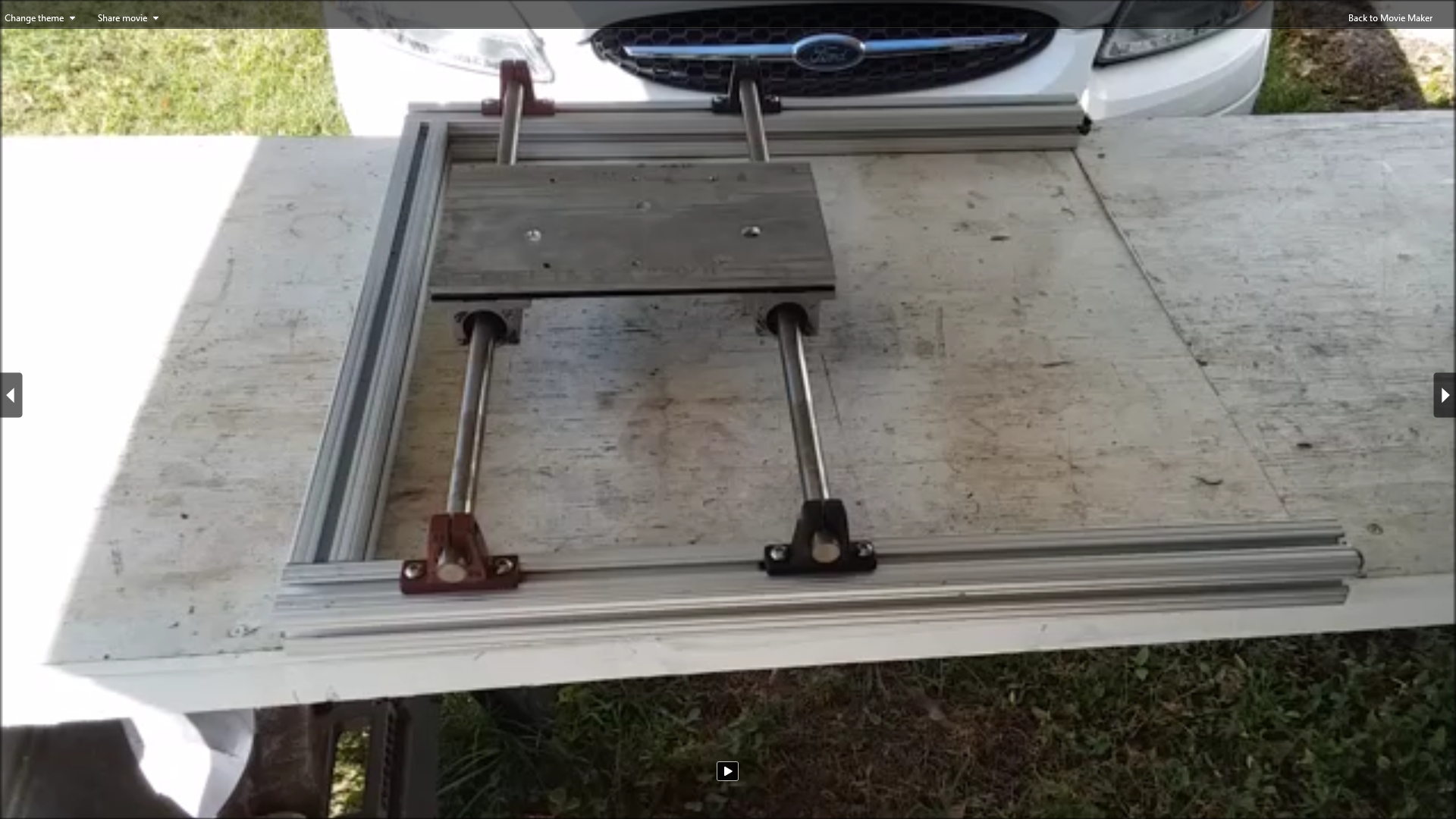
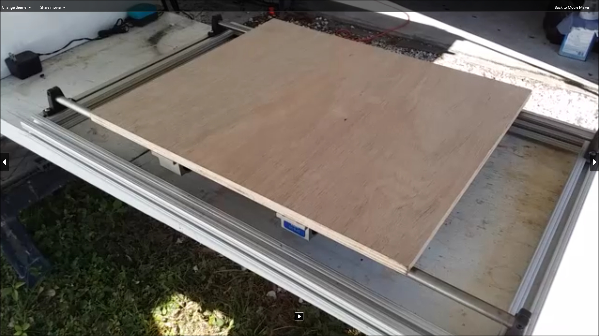 Once I had the linear rails and bearings in place, I bolted a "temporary" plywood plate on the bearings to form the x table. I did this to test the alignment and ensure the x axis
would slide smoothly without binding. Eventually I want to replace the plywood with an an aluminum plate. It may be a while before I find one. So the plywood may be temporary for quite a while.
Once I had the linear rails and bearings in place, I bolted a "temporary" plywood plate on the bearings to form the x table. I did this to test the alignment and ensure the x axis
would slide smoothly without binding. Eventually I want to replace the plywood with an an aluminum plate. It may be a while before I find one. So the plywood may be temporary for quite a while.
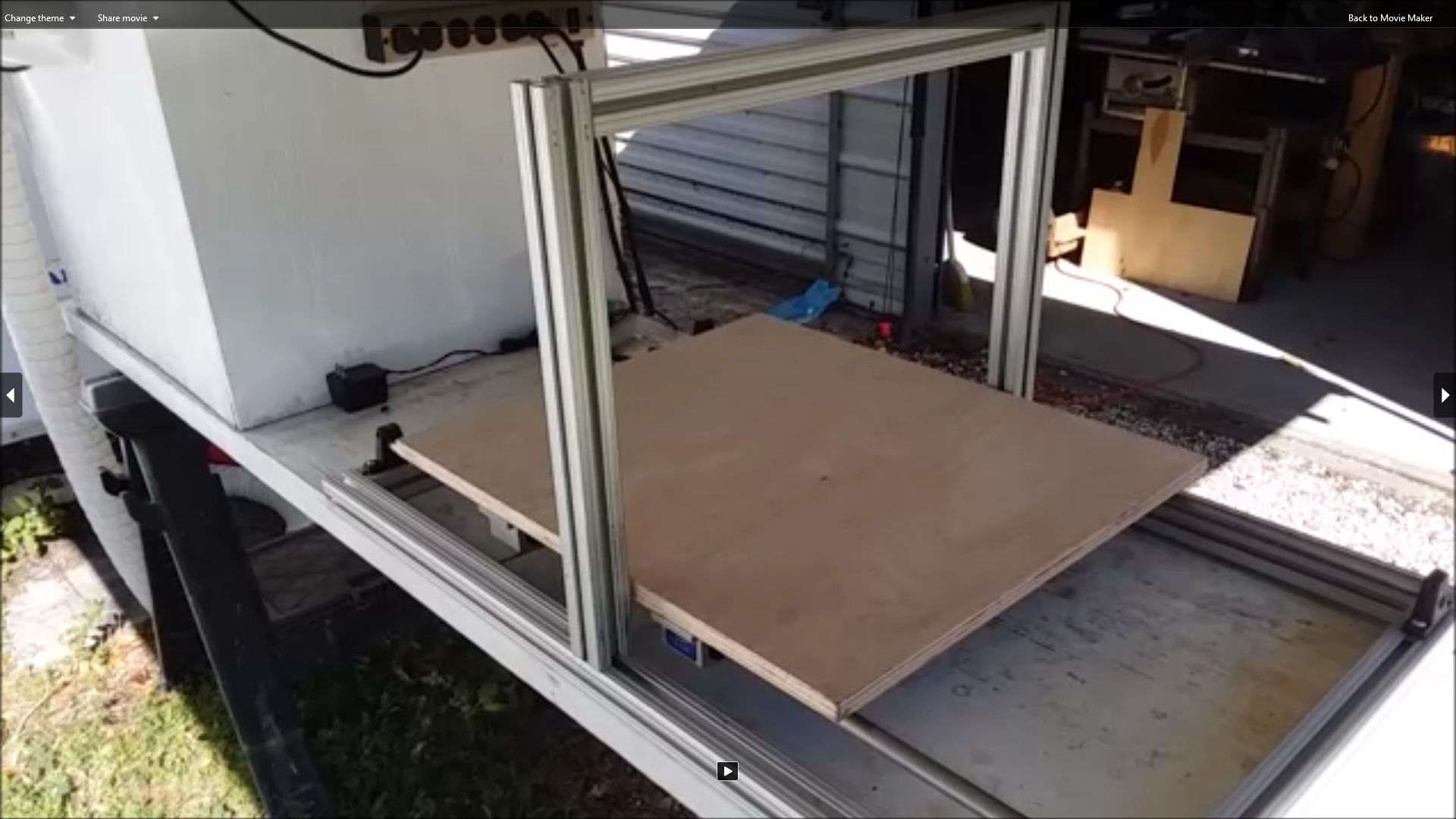 Here I have temporarily bolted a gantry that will hold the y and z axes onto the machine. This was just temporary. Later it was removed so I could more easily gain access to the underside of
the machine when it came time to mount the ballscrew for the x axis. Later I would make a somewhat taller gantry to accommodate the use of a turntable mounted on the x axis table. I would
also offset the gantry to make up for the offset of the spindle to one side of it.
Here I have temporarily bolted a gantry that will hold the y and z axes onto the machine. This was just temporary. Later it was removed so I could more easily gain access to the underside of
the machine when it came time to mount the ballscrew for the x axis. Later I would make a somewhat taller gantry to accommodate the use of a turntable mounted on the x axis table. I would
also offset the gantry to make up for the offset of the spindle to one side of it.
Looking at this setup I decided the gantry would need some stiffening and strengthening gussets when it was permanently mounted. My original plan was to make some, but I decided to use
some that got stripped off my earlier Wood Pile CNC router when I decommissioned it.
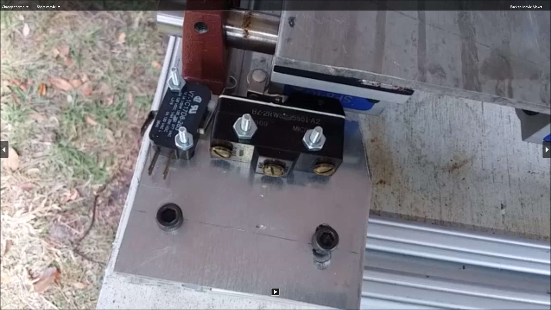
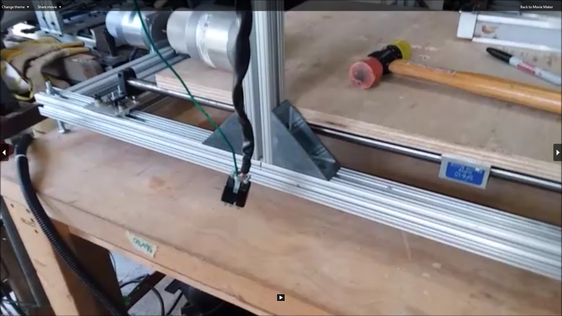
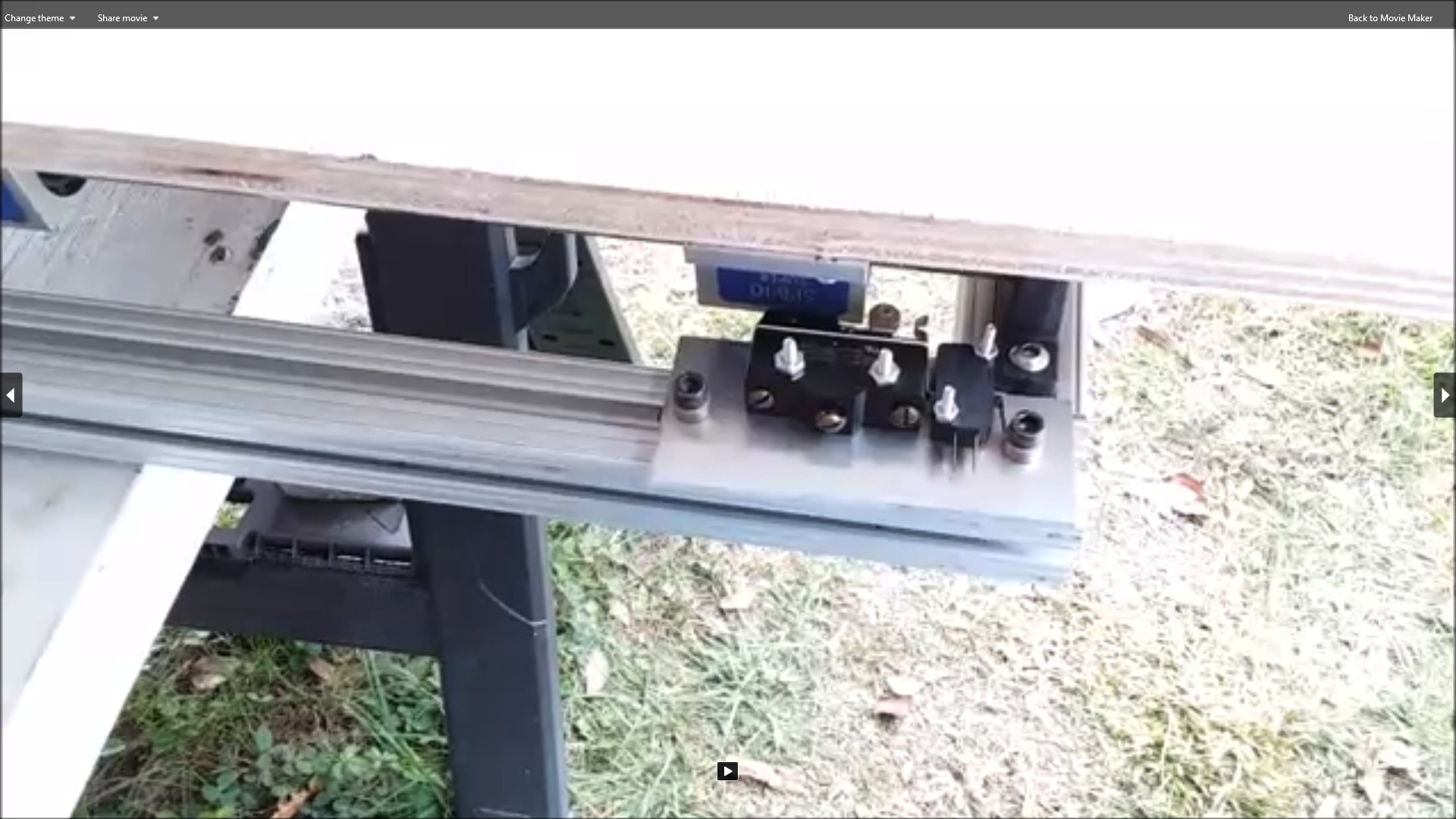 This photo shows the home and limit switches I mounted on one side of the x axis. The home switch has a wheel that will allow the switch to be activated by the side of the linear bearing as
it passes by. The home switch tells the computer driving the machine exactly where the axis is located when it is activated. The limit switch prevents the axis from moving so far that it
crashes into the rail support blocks. If the computer senses that a limit switch has been activated, it will shut down the motors. Each axis only needs one home switch, but they need a limit
switch at each end. The switches were not yet wired at this point.
This photo shows the home and limit switches I mounted on one side of the x axis. The home switch has a wheel that will allow the switch to be activated by the side of the linear bearing as
it passes by. The home switch tells the computer driving the machine exactly where the axis is located when it is activated. The limit switch prevents the axis from moving so far that it
crashes into the rail support blocks. If the computer senses that a limit switch has been activated, it will shut down the motors. Each axis only needs one home switch, but they need a limit
switch at each end. The switches were not yet wired at this point.
|
Click to learn how
to meet them
|
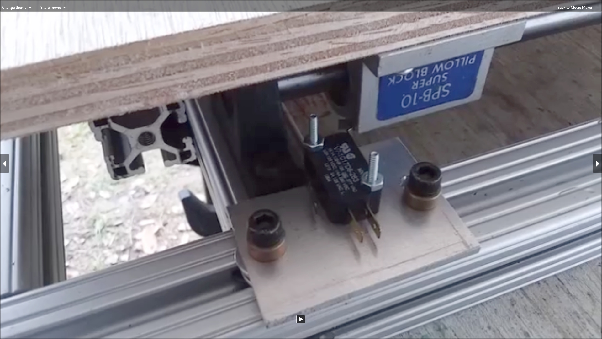 Here is a photo of the limit switch mounted on the other end of the x axis. The home and limit switches are mounted on small pieces of aluminum plate. The aluminum plate is then bolted
to the 80/20 rails with 1/4-20 socket head cap bolts and t-nuts. Enough washers were stacked between the plates and rail to raise the switches high enough for the linear bearings to
contact them.
Here is a photo of the limit switch mounted on the other end of the x axis. The home and limit switches are mounted on small pieces of aluminum plate. The aluminum plate is then bolted
to the 80/20 rails with 1/4-20 socket head cap bolts and t-nuts. Enough washers were stacked between the plates and rail to raise the switches high enough for the linear bearings to
contact them.
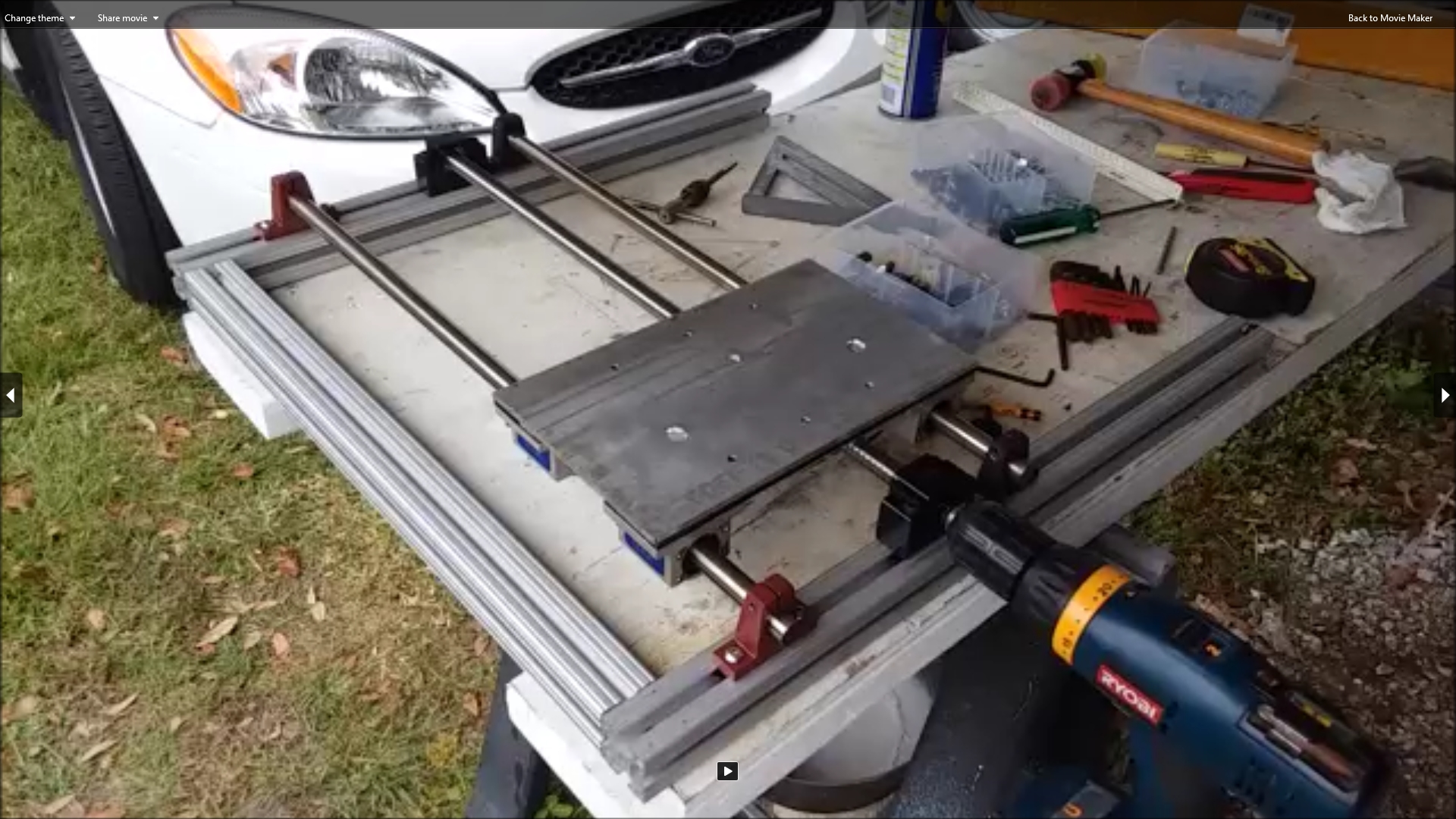
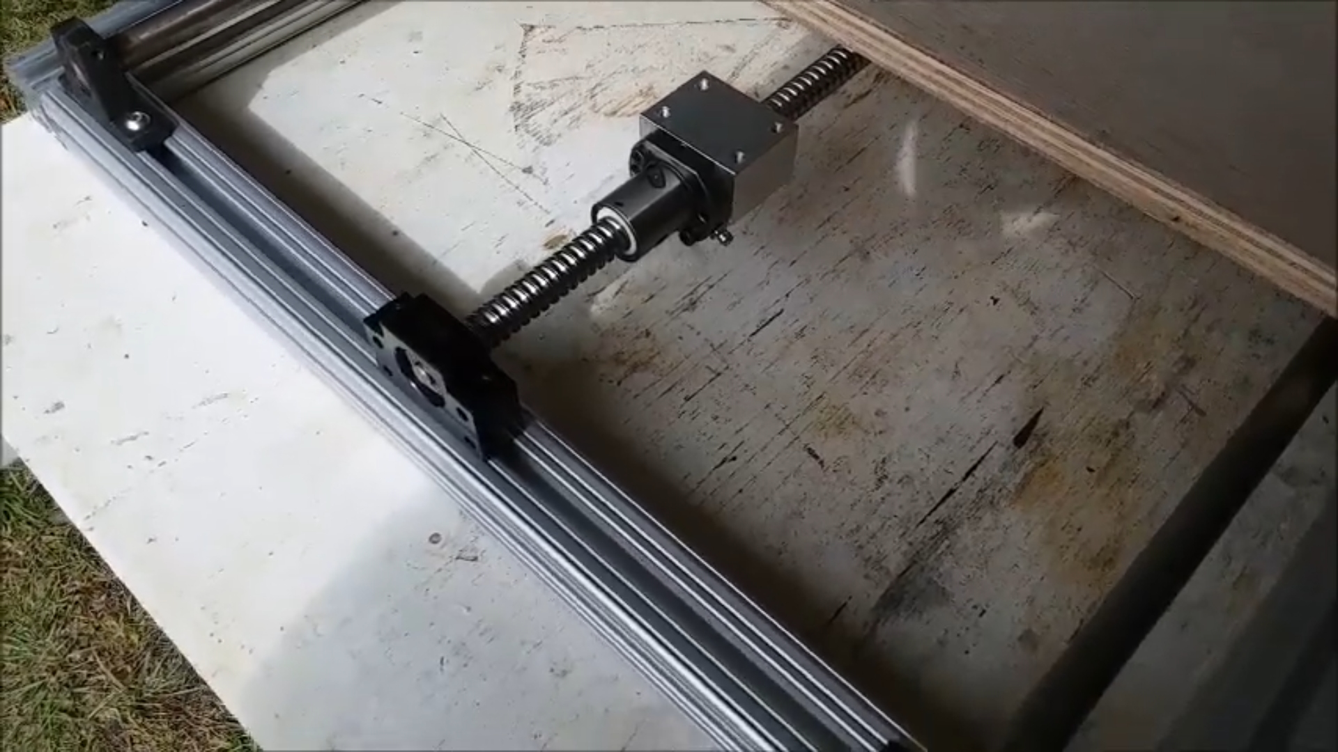 Here the x axis ballscrew, nut and bearings have just arrived and I am mocking up where they will be mounted. The ballscrew is 16mm in diameter, 1000mm long and has a 5mm pitch
(meaning the nut will travel 5mm per rotation). The mounting block (the silver rectangle with four holes in it) has been bolted onto the end of the nut. Four matching holes will
be drilled in the center of the plywood x table and bolts will pass through into the mounting block. Then as the nut moves on the screw, it will pull the table along.
Here the x axis ballscrew, nut and bearings have just arrived and I am mocking up where they will be mounted. The ballscrew is 16mm in diameter, 1000mm long and has a 5mm pitch
(meaning the nut will travel 5mm per rotation). The mounting block (the silver rectangle with four holes in it) has been bolted onto the end of the nut. Four matching holes will
be drilled in the center of the plywood x table and bolts will pass through into the mounting block. Then as the nut moves on the screw, it will pull the table along.
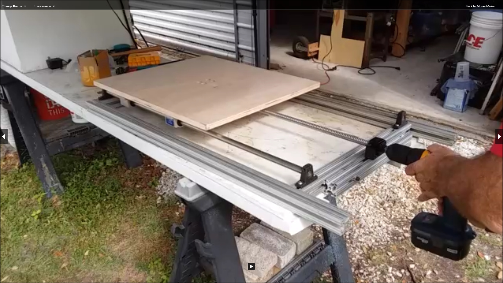 Here the ball screw and bearings have been bolted to the framework. The x table has been bolted to the mounting block. I am driving the x axis back and forth using my hand-held drill
to test that the axis moved smoothly along its entire length without binding anywhere. It was working good.
Here the ball screw and bearings have been bolted to the framework. The x table has been bolted to the mounting block. I am driving the x axis back and forth using my hand-held drill
to test that the axis moved smoothly along its entire length without binding anywhere. It was working good.
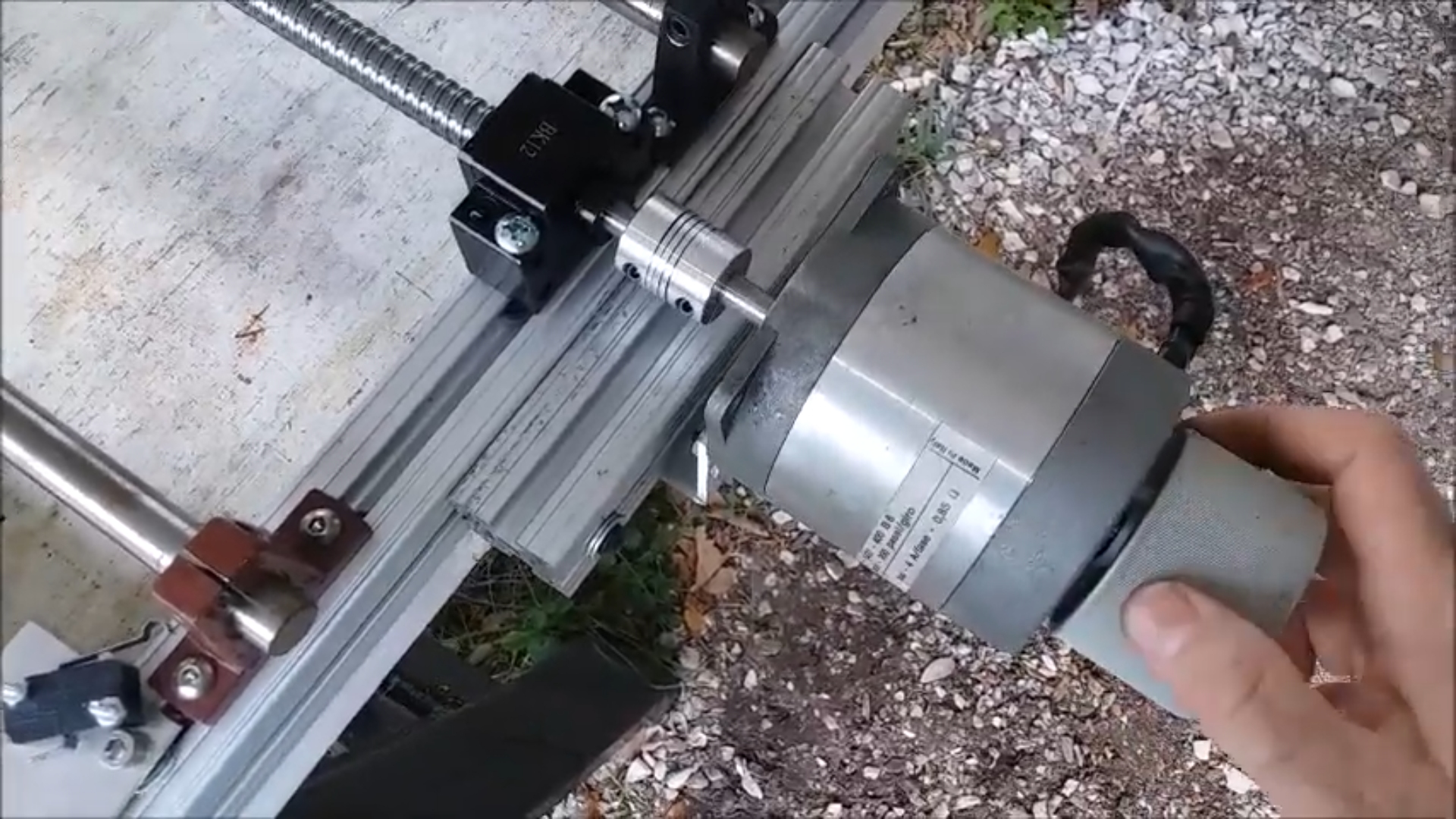
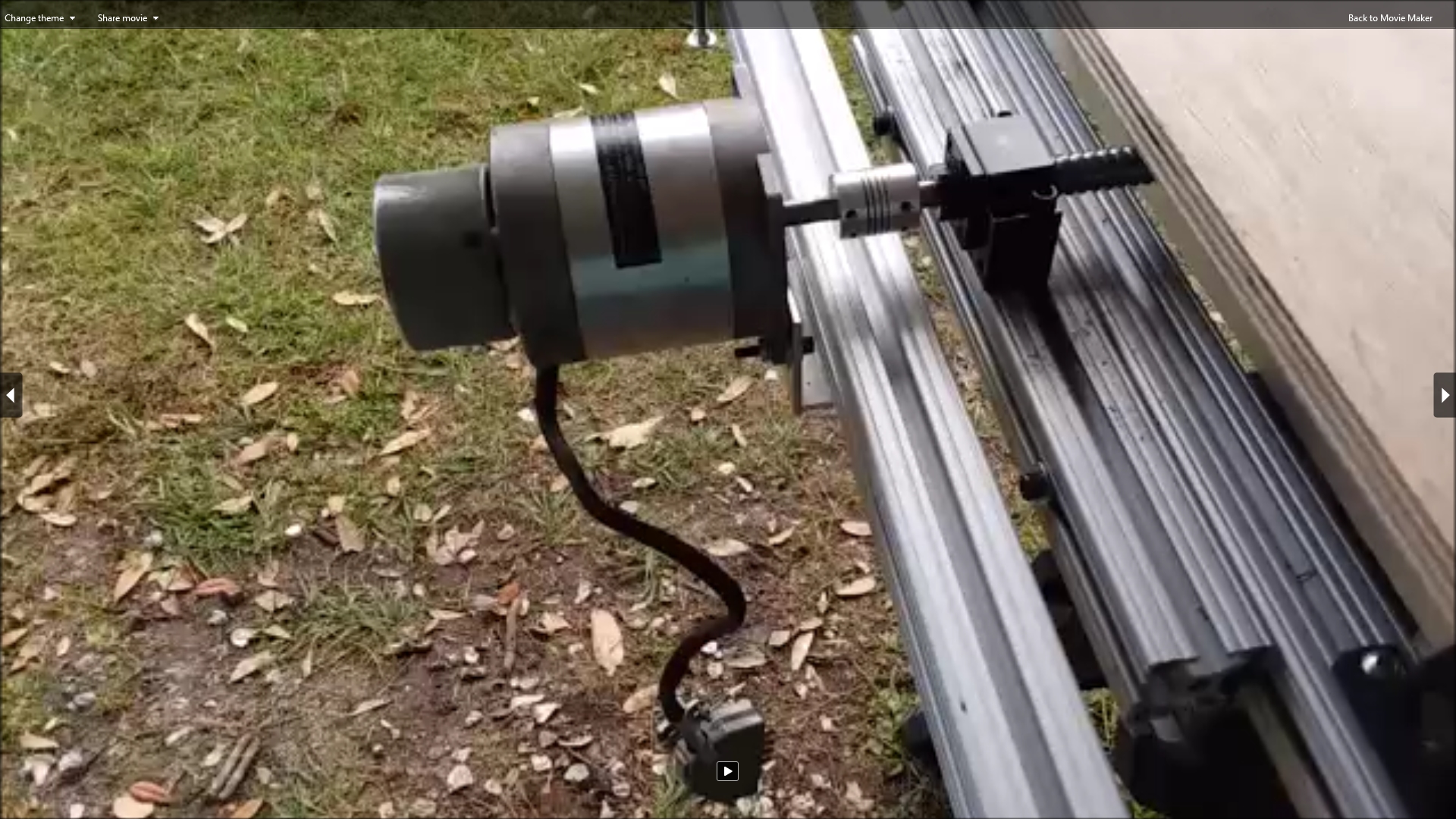 The motor for the x axis was mounted using a piece of heavy aluminum angle bracket. Holes were drilled in the bottom of the angle bracket for 1/4-20 bolts and t-nuts to mount the bracket
to the 80/20 rail wich allows side to side adjustment of the motor position. Slots were cut in the other side of the bracket to allow up and down adjustment of the motor position.
With the two dimensional adjustability I was able to pretty much perfectly align the motor shaft with the end of the ball screw. I used a spiral-cut coupler to absorb any residual
mis-alignment.
The motor for the x axis was mounted using a piece of heavy aluminum angle bracket. Holes were drilled in the bottom of the angle bracket for 1/4-20 bolts and t-nuts to mount the bracket
to the 80/20 rail wich allows side to side adjustment of the motor position. Slots were cut in the other side of the bracket to allow up and down adjustment of the motor position.
With the two dimensional adjustability I was able to pretty much perfectly align the motor shaft with the end of the ball screw. I used a spiral-cut coupler to absorb any residual
mis-alignment.
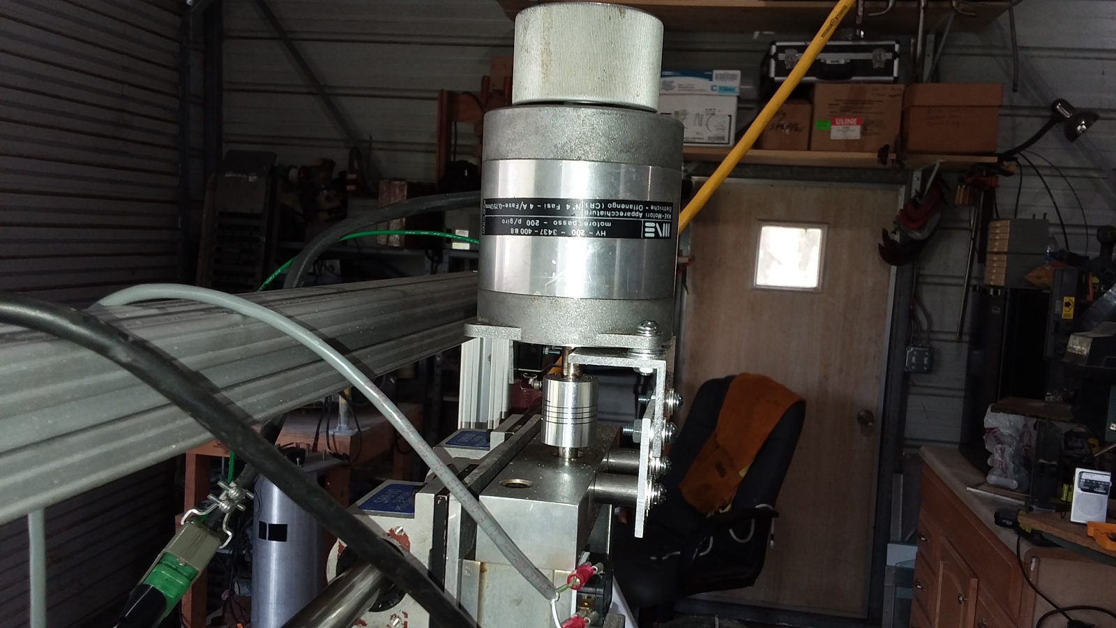
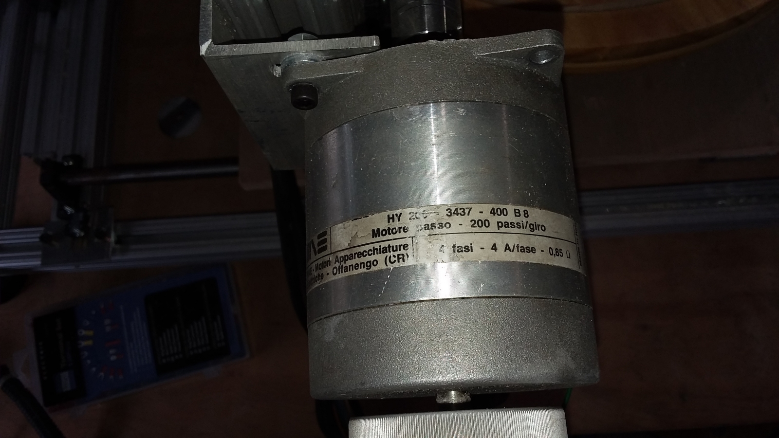 Here is a close-up of one of the stepper motors I used. I used three identical motors. One for each of the three axes. I'm not sure what language that is, but the essentials are understandable. They are
200 step per rotation (1.8 degree per step), 4-wire (bipolar), 0.85 Ohm per phase, 4 Amps per phase, and they are big and powerful motors. I got these motors from some old, retired CNC lathes. They moved a very heavy
headstock using a similar ballscrew arrangement to what I am building. The motors are quite old, but still all work great. I decided to use them on this project rather than buy new motors. They are NEMA frame 34 for
mounting hole layout, but may be so old that they may pre-date the standard.
I may in the future buy some proper NEMA frame 34 mounting plates and replace my home-made mountings to increase the rigidity of the mounting.
Here is a close-up of one of the stepper motors I used. I used three identical motors. One for each of the three axes. I'm not sure what language that is, but the essentials are understandable. They are
200 step per rotation (1.8 degree per step), 4-wire (bipolar), 0.85 Ohm per phase, 4 Amps per phase, and they are big and powerful motors. I got these motors from some old, retired CNC lathes. They moved a very heavy
headstock using a similar ballscrew arrangement to what I am building. The motors are quite old, but still all work great. I decided to use them on this project rather than buy new motors. They are NEMA frame 34 for
mounting hole layout, but may be so old that they may pre-date the standard.
I may in the future buy some proper NEMA frame 34 mounting plates and replace my home-made mountings to increase the rigidity of the mounting.
 Here I have just completed putting together the linear rails and bearings for the y axis. The liner bearings are mounted on an aluminum plate that the z axis will eventually be mounted to.
The setup is similar to the x axis, but smaller in width and travel distance. The y axis rails are only 24 inches long.
Here I have just completed putting together the linear rails and bearings for the y axis. The liner bearings are mounted on an aluminum plate that the z axis will eventually be mounted to.
The setup is similar to the x axis, but smaller in width and travel distance. The y axis rails are only 24 inches long.
|
Click to learn how
to meet them
|
 Home and limit switches were mounted on the y axis very similarly to how they were mounted on the x axis.
 Eventually the ball screw, nut bearings and mounting block arrived for the y axis and I was able to mount them. The ballscrew for the y axis is the same diameter (16mm) and pitch (5mm) as the x axis,
but shorter. It is only 600mm long. Here I am driving this axis back and forth with my drill to ensure it moves smoothly.
Eventually the ball screw, nut bearings and mounting block arrived for the y axis and I was able to mount them. The ballscrew for the y axis is the same diameter (16mm) and pitch (5mm) as the x axis,
but shorter. It is only 600mm long. Here I am driving this axis back and forth with my drill to ensure it moves smoothly.
 The y axis motor was mounted in exactly the same manner as the x axis motor.
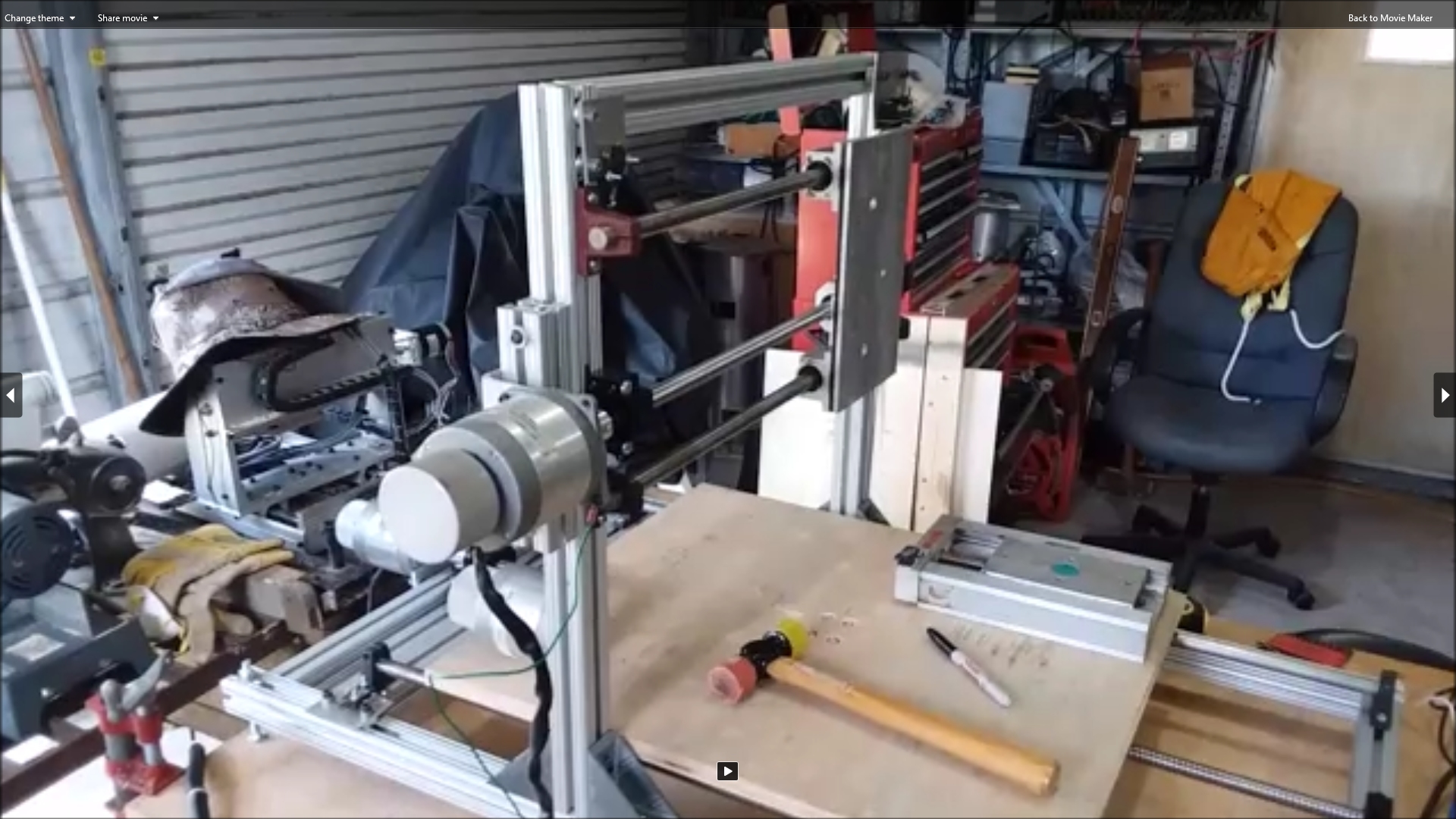 Here the y axis has been mounted on the x axis frame. The machine was really starting to come together by this point.
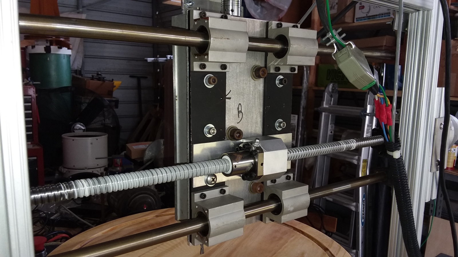 Here is a view of the back of the y axis showing how everything is put together. The three large socket-head bolts hold the z axis in place.
 I installed gussets on the gantry for the y axis to improve rigidity. These gussets areavailable from 80/20 specifically for use with their rail. I salvaged these gussets from the old Woodpile
CNC router when I retired it. The gussets were bolted into place with the usual socket head 1/4-20 cap screws and t-nuts.
I installed gussets on the gantry for the y axis to improve rigidity. These gussets areavailable from 80/20 specifically for use with their rail. I salvaged these gussets from the old Woodpile
CNC router when I retired it. The gussets were bolted into place with the usual socket head 1/4-20 cap screws and t-nuts.
|
Click to learn how
to meet them
|
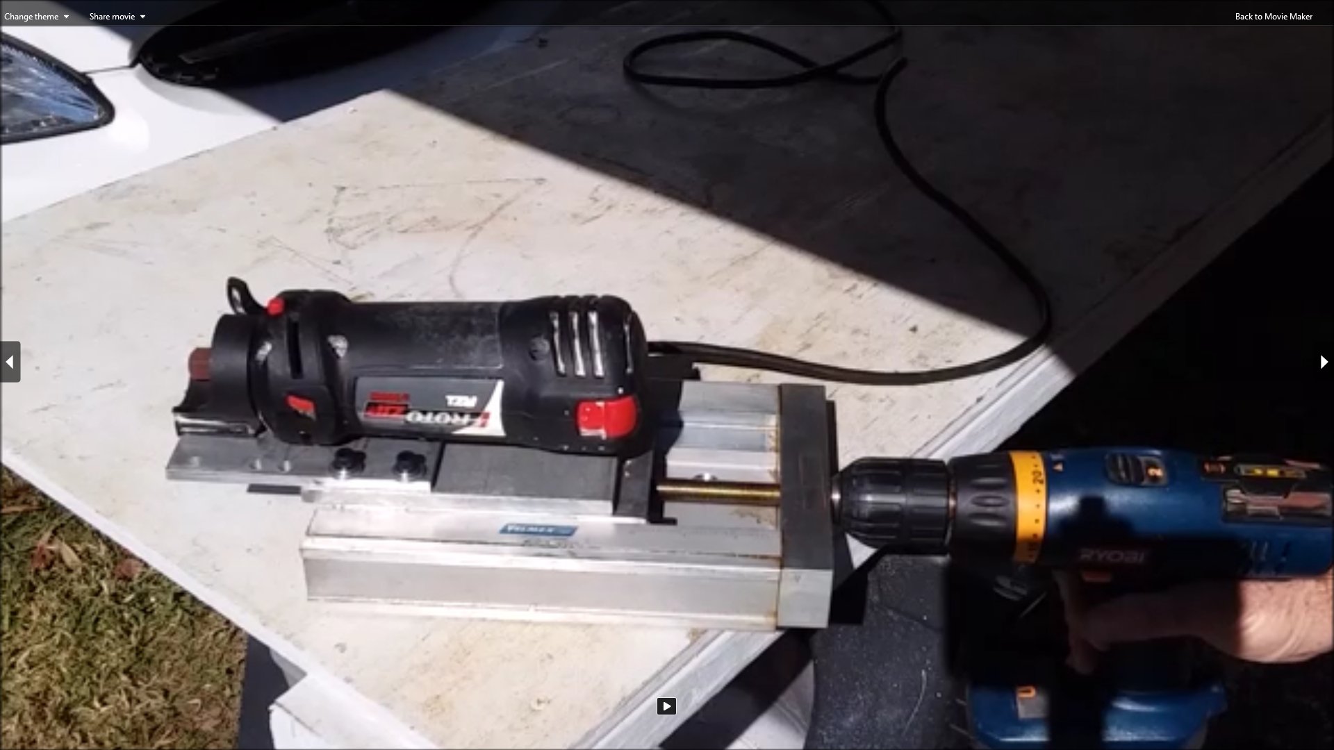 Here I am test driving the z axis with my drill. The z axis is quite different from the other two. It is a pre-made unit. It is a Velmex Unislide linear platform. It is designed for three inches of travel.
I removed the bottom plate that stops it after three inches and can get another inch out of it with no real issues. I got a couple of these Velmex units when a company I used to work for closed down.
They can also be found used on Ebay, or purchased new from Velmex for lots of $$$$.
I used one of these Unislides on the old Woodpile CNC, and it worked great. So I decided to use the other on this new machine. This unit has a 20 turns to the inch leadscrew in it. So this axis will need to be tuned
quite differently from the other two.
Here I am test driving the z axis with my drill. The z axis is quite different from the other two. It is a pre-made unit. It is a Velmex Unislide linear platform. It is designed for three inches of travel.
I removed the bottom plate that stops it after three inches and can get another inch out of it with no real issues. I got a couple of these Velmex units when a company I used to work for closed down.
They can also be found used on Ebay, or purchased new from Velmex for lots of $$$$.
I used one of these Unislides on the old Woodpile CNC, and it worked great. So I decided to use the other on this new machine. This unit has a 20 turns to the inch leadscrew in it. So this axis will need to be tuned
quite differently from the other two.
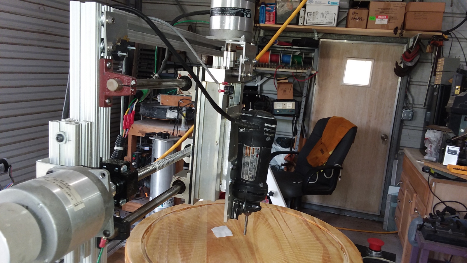
Bolted on the Unislide is an old RotoZip I've been holding on to for just this sort of application. The RotoZip is actually bolted onto a piece of thick aluminum plate, and the plate is bolted to the
Unislide. The RotoZip will serve as the spindle for the machine. I used a RotoZip on the old Woodpile CNC machine and it worked well.
 Mounting the motor on the z axis was a bit more difficult than than the other axis. There were no convenient 80/20 slotted rails to mount it to. So I had to drill and tap a couple of holes in the top of
the Unislide. Then I mounted a slotted aluminum bracket on tall steel standoffs. From there the rest of the mounting was similar to the other two axes.
Mounting the motor on the z axis was a bit more difficult than than the other axis. There were no convenient 80/20 slotted rails to mount it to. So I had to drill and tap a couple of holes in the top of
the Unislide. Then I mounted a slotted aluminum bracket on tall steel standoffs. From there the rest of the mounting was similar to the other two axes.
 With the z axis completed, it was time to mount it on the machine It is held on the y axis plate with three large socket head cap bolts.
This photo also shows the z axis home switch. At present this axis doesn't have limit switches.
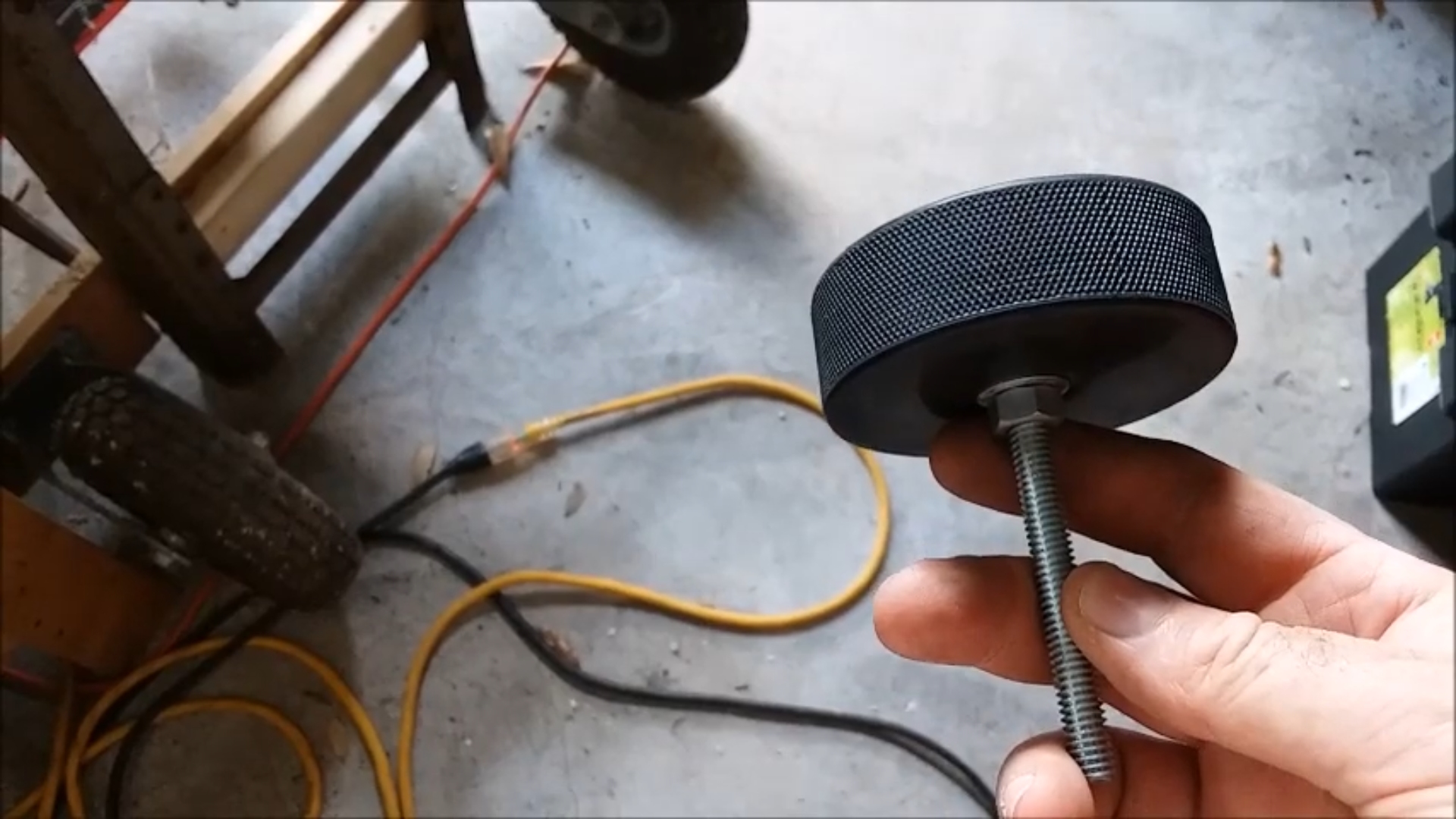 At this point I decided the machine needed some decent feet to stand on. They needed to be vibration absorbing, anti-skid and allow me to level the machine. I made four feet using hockey pucks
and counter-sunk carriage bolts. I have used feet like this on all kinds of equipment. They are cheap and easy to make, and work great.
At this point I decided the machine needed some decent feet to stand on. They needed to be vibration absorbing, anti-skid and allow me to level the machine. I made four feet using hockey pucks
and counter-sunk carriage bolts. I have used feet like this on all kinds of equipment. They are cheap and easy to make, and work great.
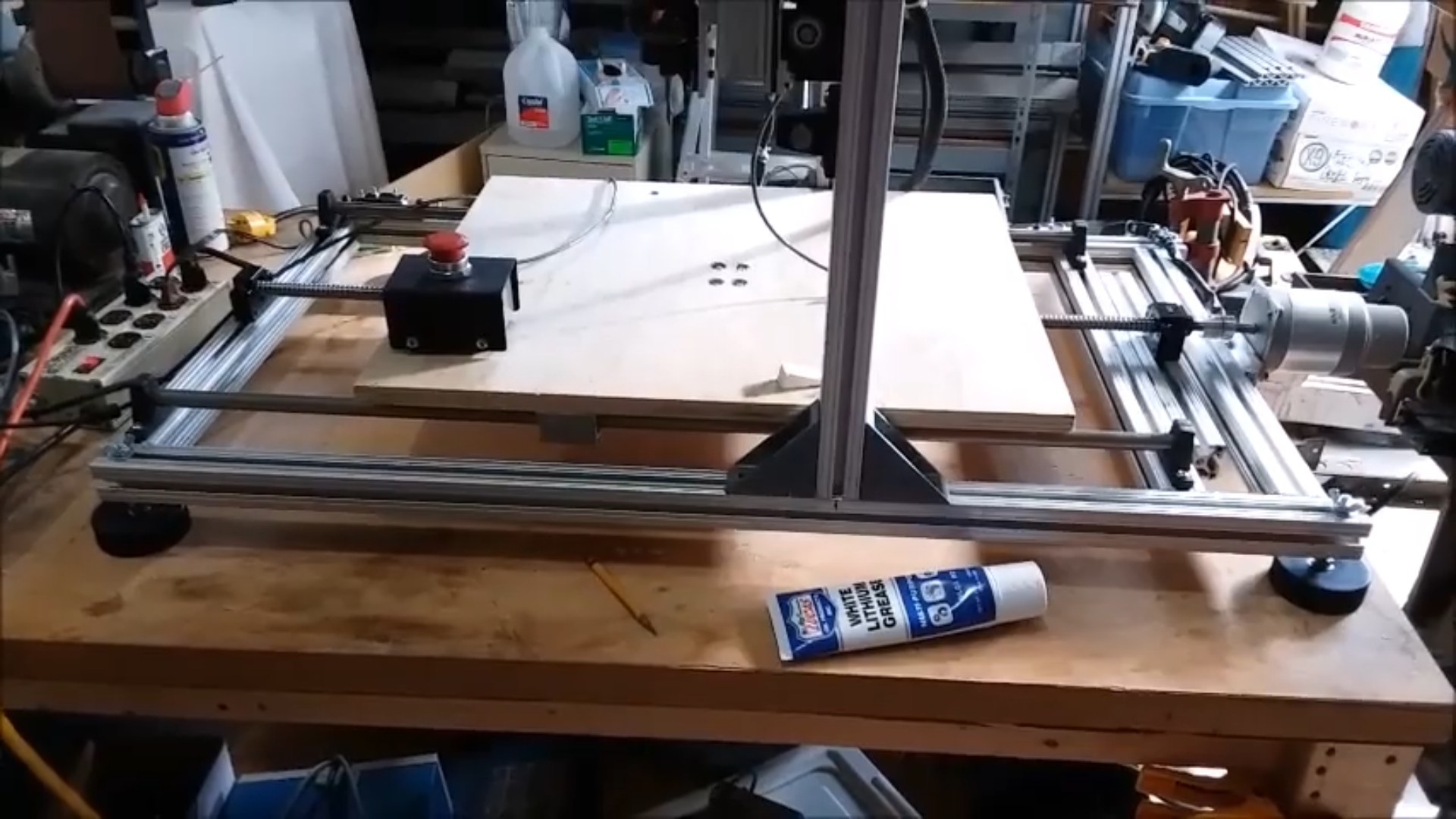 Here is the machine sitting on it's four new hockey puck feet, all leveled up and ready to roll. I may add two more feet in the center of the long rails to prevent the rails from bowing over time
under the weight of the y and z axes, plus cutting forces. So far that hasn't been a problem.
Here is the machine sitting on it's four new hockey puck feet, all leveled up and ready to roll. I may add two more feet in the center of the long rails to prevent the rails from bowing over time
under the weight of the y and z axes, plus cutting forces. So far that hasn't been a problem.
|
Click to learn how
to meet them
|
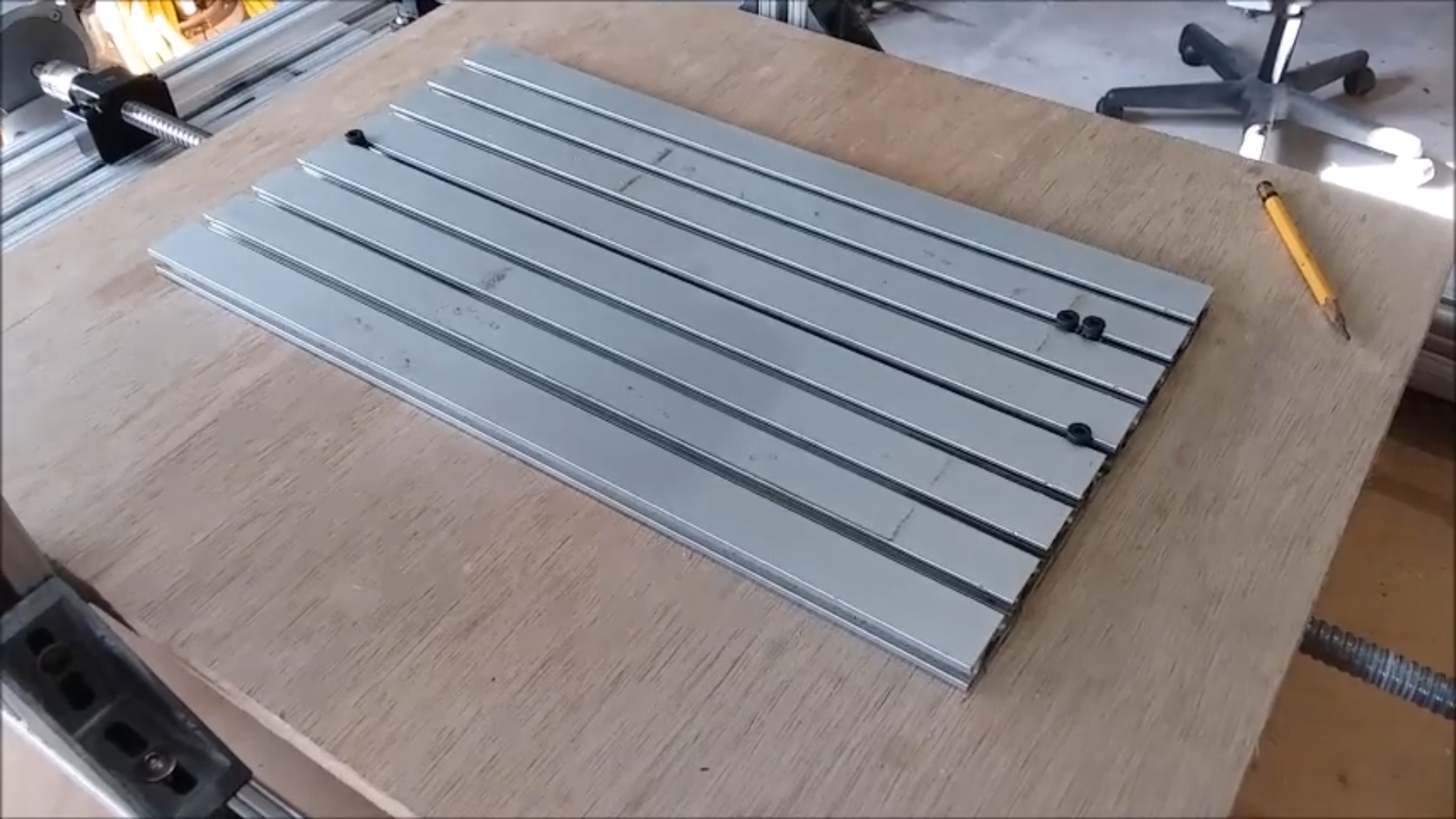 I happened to have some extruded aluminum t-slot plate on hand which was salvaged from a much smaller machine. I decided to bolt it onto the x axis table. This t-slot plate will allow me to more
easily bolt things onto the x table for machining. My eventual plan is to replace the wood table and small t-slot plate with an aluminum table and full size t-slot plate. That may not happen for
a while.
I happened to have some extruded aluminum t-slot plate on hand which was salvaged from a much smaller machine. I decided to bolt it onto the x axis table. This t-slot plate will allow me to more
easily bolt things onto the x table for machining. My eventual plan is to replace the wood table and small t-slot plate with an aluminum table and full size t-slot plate. That may not happen for
a while.
At this point the mechanical part of the machine build was complete. It was time to turn to working on the electronics. In reality the mechanical and electronic work went on concurrently.
The video at the top of the page kind of jumps back and forth between the two. For clarity here I have separated them on this web page.
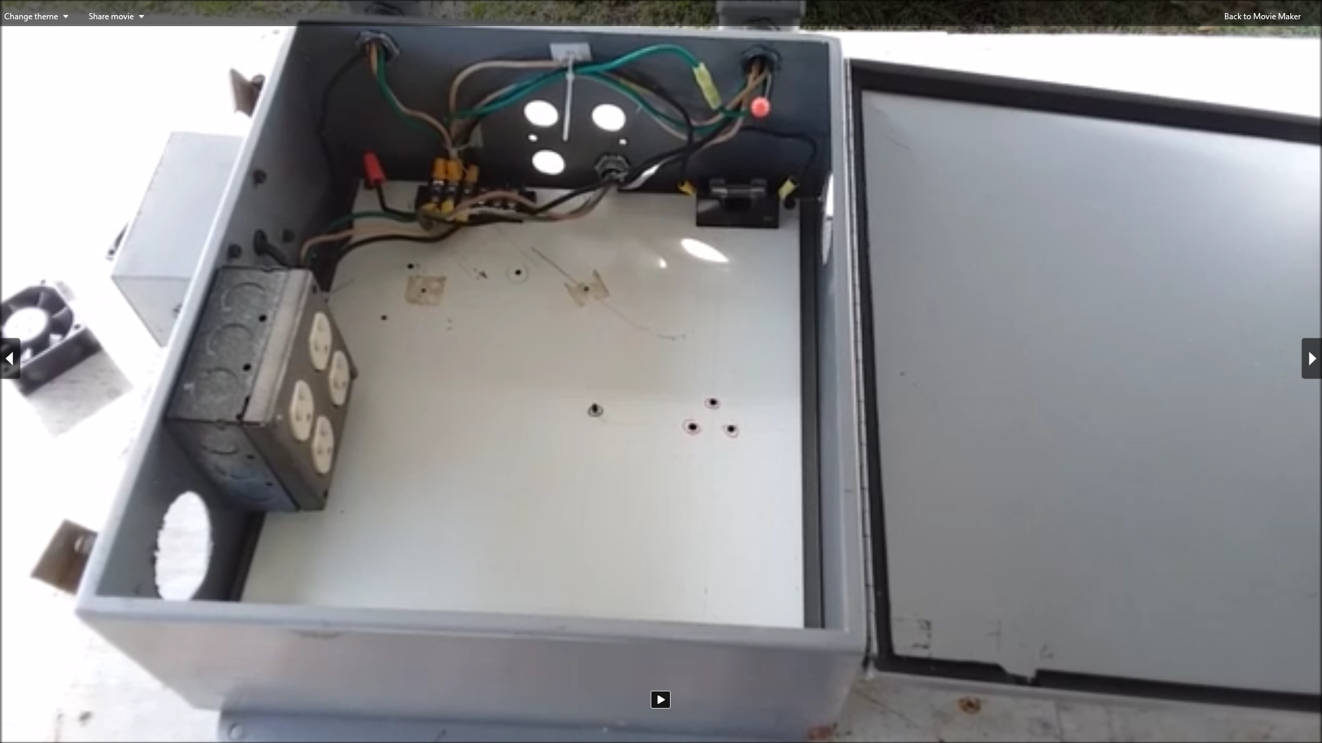 This large metal enclosure will hold all the electronics for the machine. This box was salvaged from a large industrial machine that was retired. It was full of old-school relays
and mechanical switching equipment. I gutted it and put a four gang power outlet inside to plug in stuff. There is a power switch mounted on the side of the box. There are also some
external outlets that are switched by the power switch. There are other external outlets that will eventually be switched under computer control for the spindle and vacuum power.
This large metal enclosure will hold all the electronics for the machine. This box was salvaged from a large industrial machine that was retired. It was full of old-school relays
and mechanical switching equipment. I gutted it and put a four gang power outlet inside to plug in stuff. There is a power switch mounted on the side of the box. There are also some
external outlets that are switched by the power switch. There are other external outlets that will eventually be switched under computer control for the spindle and vacuum power.
When I took this photo I had just cut big holes in the sides of the box for some cooling fans.
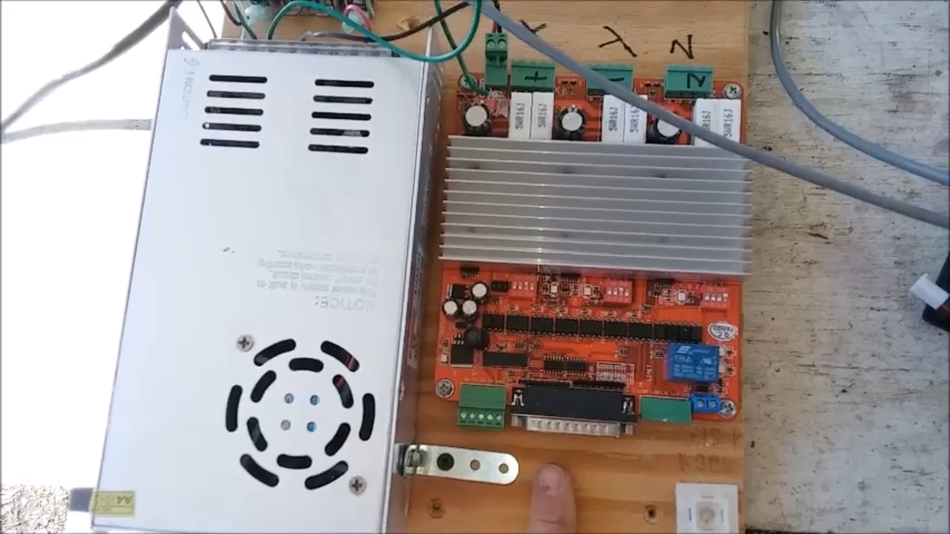 This photo shows the 24V 25A power supply (left) and the motor driver board (right) that I salvaged from the old Woodpile CNC machine when I retired it. These will be mounted in the
above enclosure.
This photo shows the 24V 25A power supply (left) and the motor driver board (right) that I salvaged from the old Woodpile CNC machine when I retired it. These will be mounted in the
above enclosure.
The driver board is designed to be used via a parallel port interface. Parallel ports are getting rarer and rarer on modern computers. I found a cheap and easy way to drive this board
from a USB port. See below.
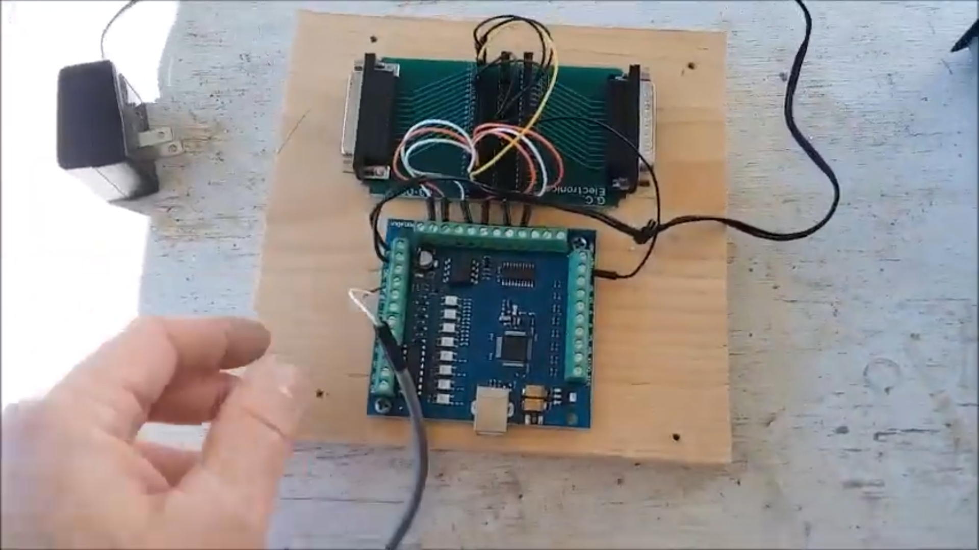 Here is a photo of the 4 Axis USB CNC Motion Controller Card Breakout Board (lower board) that I found dirt cheap on Amazon. Lots of people are selling this board or one like it on both Amazon and
Ebay. It interfaces to the controlling computer via USB, and breaks out all the motor control, switch input, output, spindle control, etc., lines on headers. I happened to have and
old RS-232 breakout board in my junk box (upper board). It uses the same 25 pin D-Shell connector as a parallel port. I ran jumper wires from the USB board to the breakout board for the signals
needed to run the driver board over a parallel cable. This way I can still use my parallel only driver board with a USB only computer. This is a very handy solution for driving older CNC
equipment that needs a parallel port. This is how I was running the Woodpile CNC before I retired it. I had gotten tired of having to bust out the old Windows XP computer when I wanted to
rout something. It was nice to be able to work from my Windows 10 laptop instead. I'll use the same setup on this new machine.
Here is a photo of the 4 Axis USB CNC Motion Controller Card Breakout Board (lower board) that I found dirt cheap on Amazon. Lots of people are selling this board or one like it on both Amazon and
Ebay. It interfaces to the controlling computer via USB, and breaks out all the motor control, switch input, output, spindle control, etc., lines on headers. I happened to have and
old RS-232 breakout board in my junk box (upper board). It uses the same 25 pin D-Shell connector as a parallel port. I ran jumper wires from the USB board to the breakout board for the signals
needed to run the driver board over a parallel cable. This way I can still use my parallel only driver board with a USB only computer. This is a very handy solution for driving older CNC
equipment that needs a parallel port. This is how I was running the Woodpile CNC before I retired it. I had gotten tired of having to bust out the old Windows XP computer when I wanted to
rout something. It was nice to be able to work from my Windows 10 laptop instead. I'll use the same setup on this new machine.
,
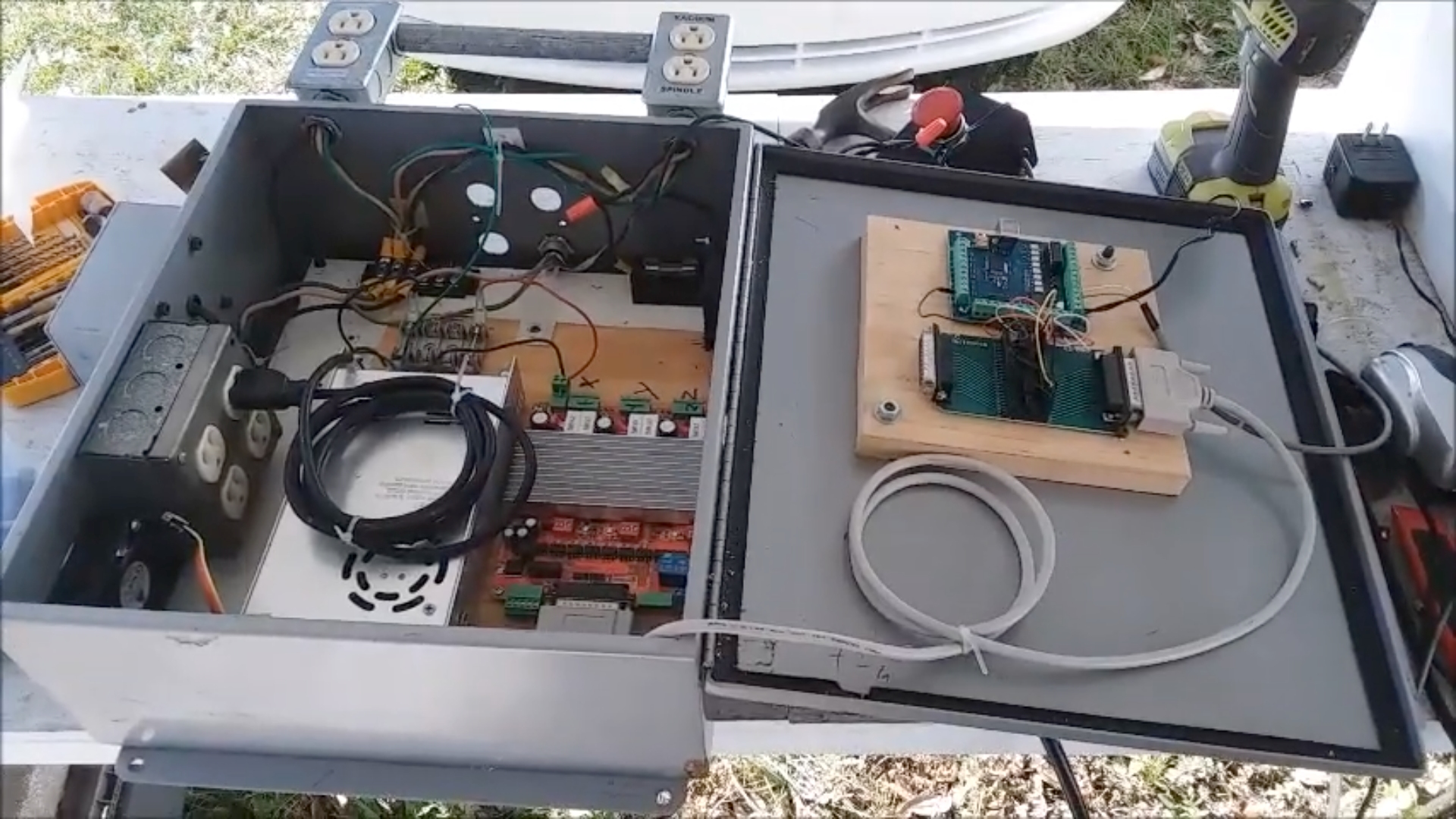 Here the boards and fans have been mounted in the electronics enclosure. I have just started running the wires and cables. There is a lot more wiring to be done.
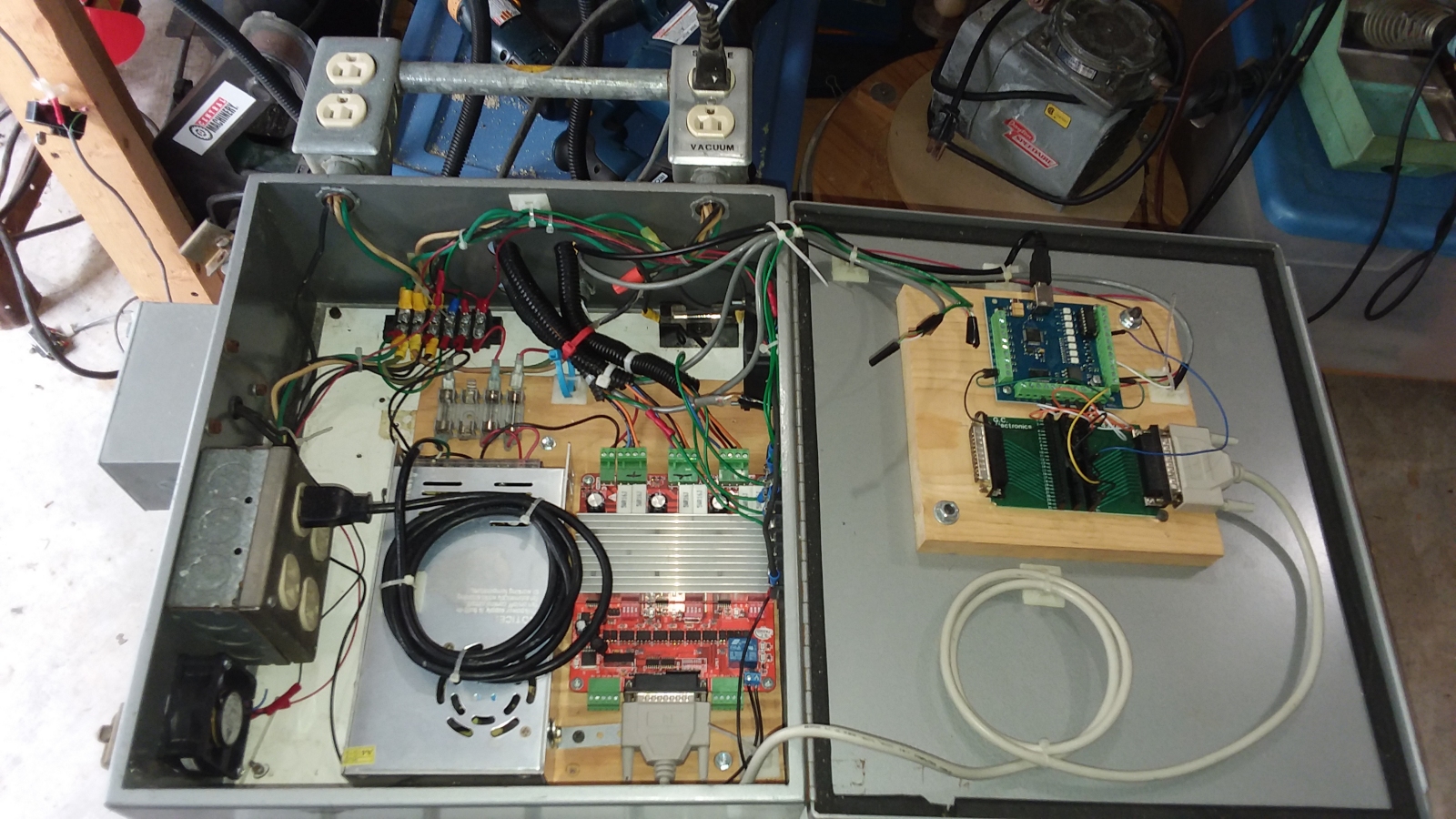 In this photo the wiring in the electronics box is mostly done, and far enough along to begin testing. The motors, e-stop switch and spindle are all wired in and working. Now I could
take a break from wiring and do some motion tests and motor tuning.
In this photo the wiring in the electronics box is mostly done, and far enough along to begin testing. The motors, e-stop switch and spindle are all wired in and working. Now I could
take a break from wiring and do some motion tests and motor tuning.
|
Click to learn how
to meet them
|
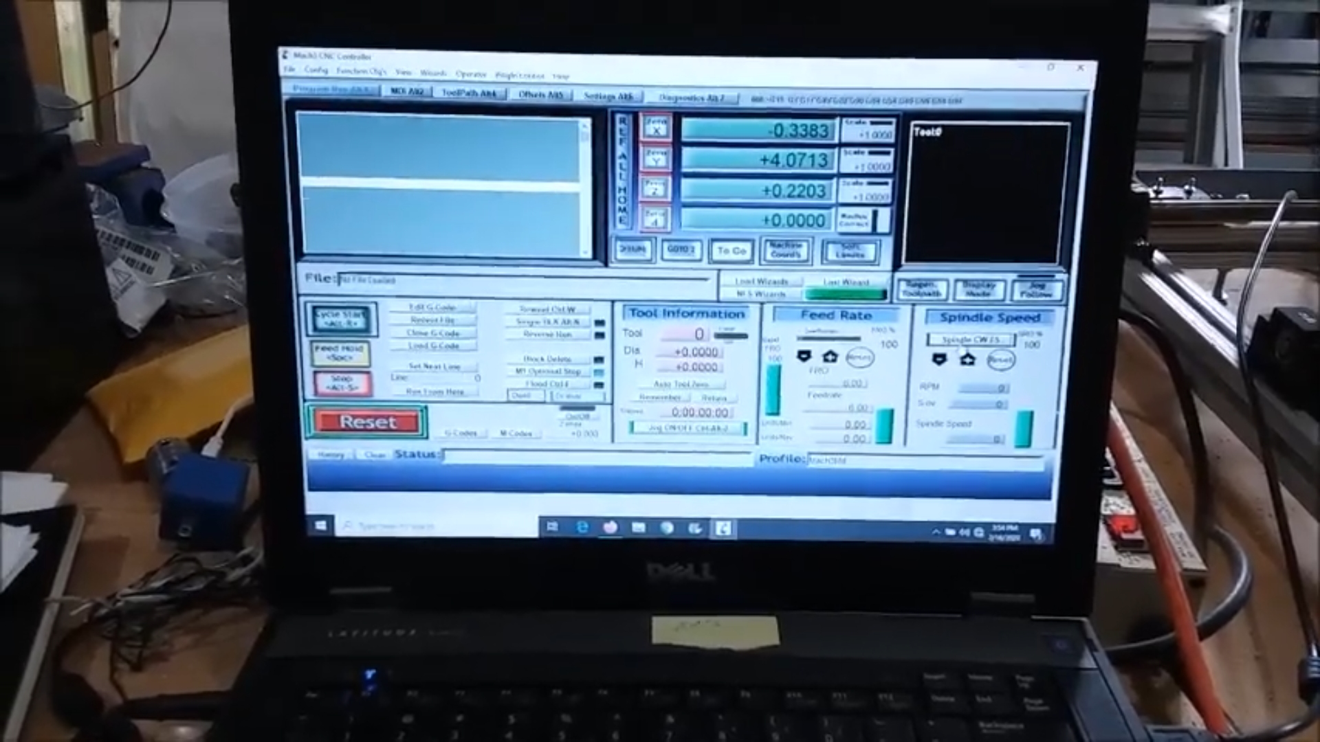 This photo shows Mach 3 running on my Windows 10 laptop. I spent about an hour and a half doing some motion testing and motor tuning in the Mach 3 software. Getting the x and y
axes tuned was pretty easy. And since they both used the same sort of screw, once I had the settings figured out for one axis, I just copied them to the other and it worked fine.
The problem child was the z axis. It took me a long time to find settings that would allow for smooth motion at a reasonable speed, without losing steps.
This photo shows Mach 3 running on my Windows 10 laptop. I spent about an hour and a half doing some motion testing and motor tuning in the Mach 3 software. Getting the x and y
axes tuned was pretty easy. And since they both used the same sort of screw, once I had the settings figured out for one axis, I just copied them to the other and it worked fine.
The problem child was the z axis. It took me a long time to find settings that would allow for smooth motion at a reasonable speed, without losing steps.
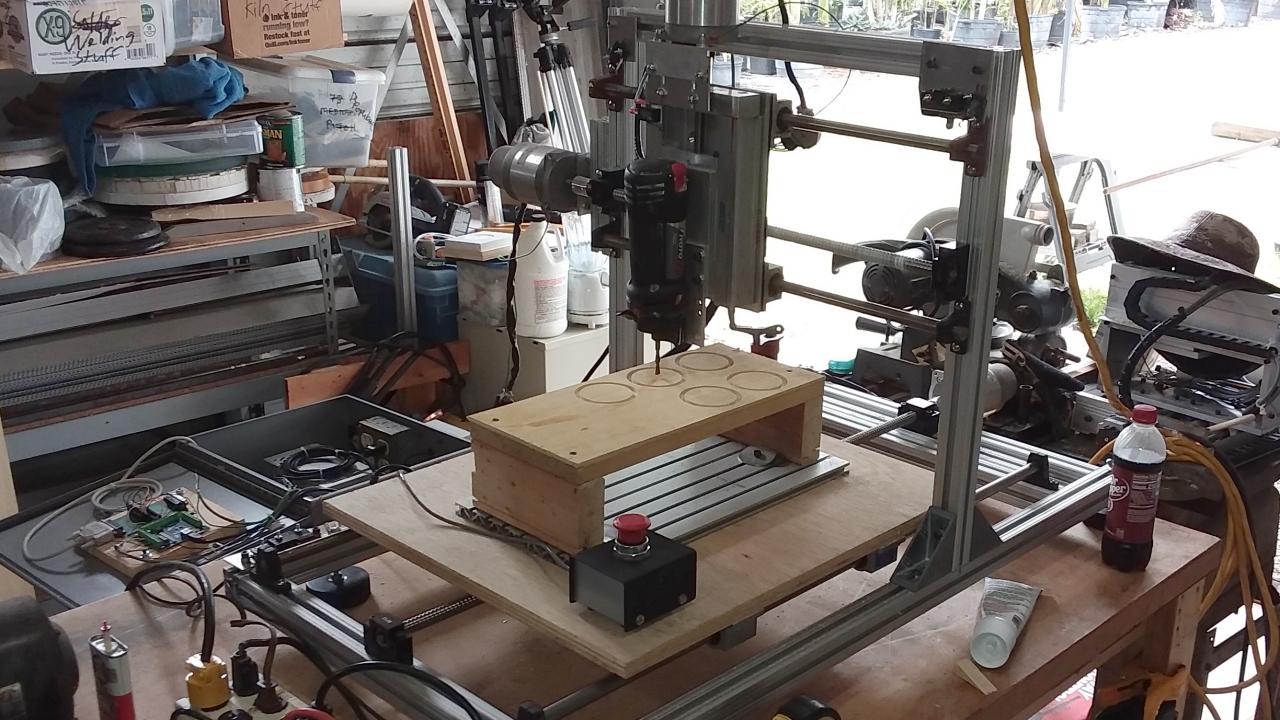
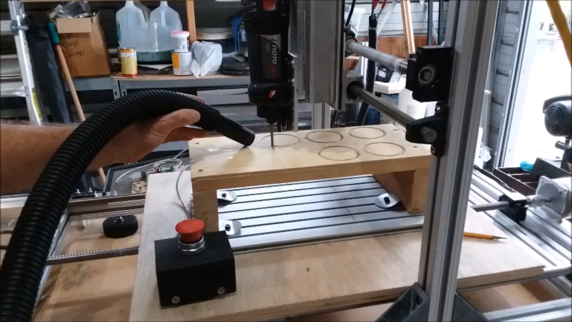 Once I had the axes moving, the next step was to do some test cuts and make any needed adjustments to to the settings. I built a raised table so I could make some cuts in plywood.
the table is needed because of the limited z axis travel, and the fact that I built this machine to accommodate a turntable mounted on the x axis.
Once I had the axes moving, the next step was to do some test cuts and make any needed adjustments to to the settings. I built a raised table so I could make some cuts in plywood.
the table is needed because of the limited z axis travel, and the fact that I built this machine to accommodate a turntable mounted on the x axis.
Cutting test circles is a good place to start. I cut some 3 inch
diameter circles to check the diameter along both the x and y axes, and look for any signs of backlash, which would be apparent at the points on the circle where the axes changed
direction. I am hand-holding the vacuum nozzle because I haven't had a chance to mount it on the machine yet. The vacuum is also still under manual control.
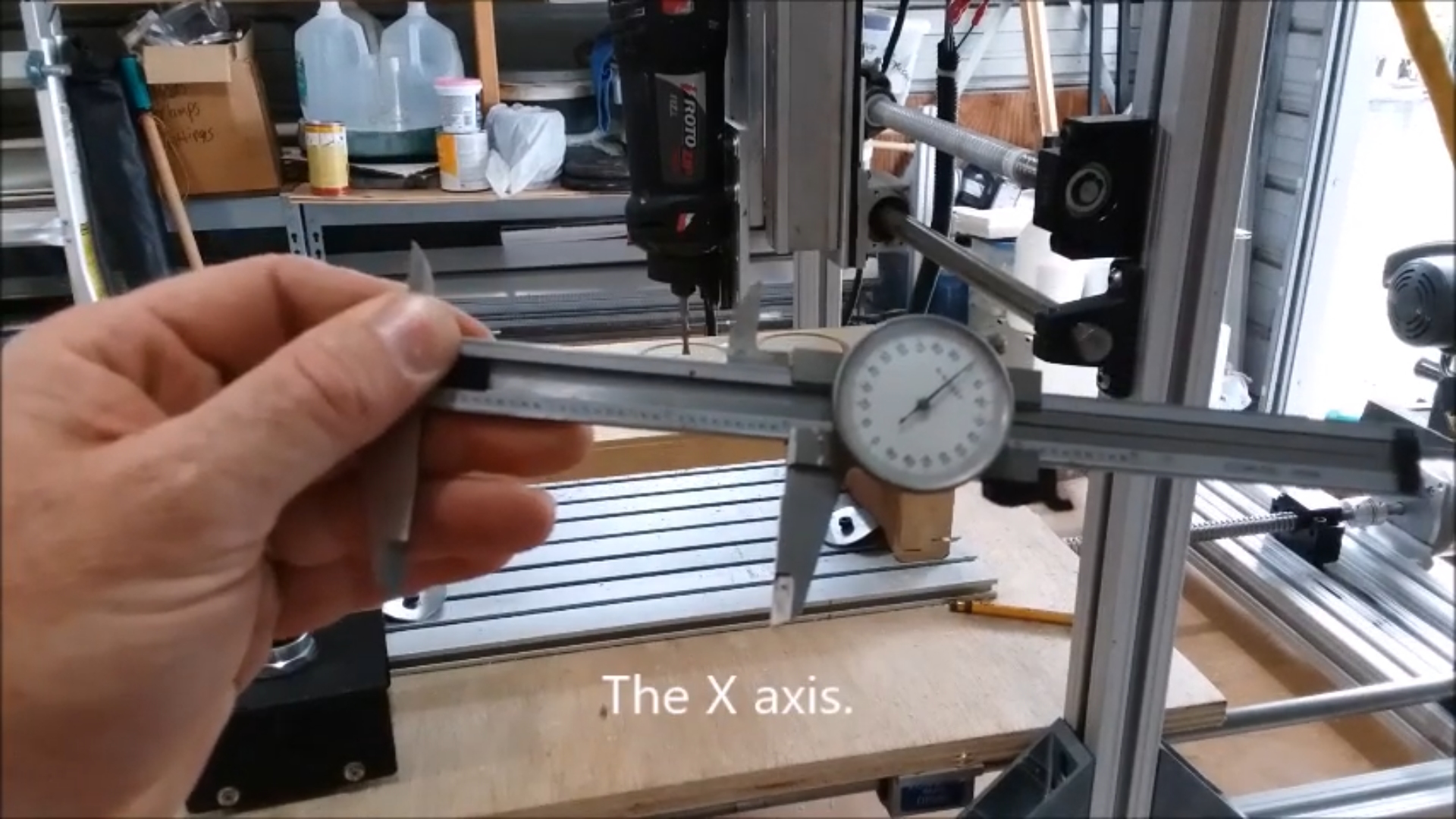 I measured the diameter of the circles. They started out a bit under-sized. After a few tweaks to the tuning, they were coming out perfect. Here my My dial caliper is showing 3.000 inches.
I think that was luck on that measurement more than skill. The circles generally measured a thousandth or two over or under, and varied a thou or so from axis to axis. That is likely due the way
the wood grain tore out during the cut. To get a more accurate measurement I'd need to cut metal. This machine should be able to make cuts in aluminum. If I cut metal in the future, I will repeat this test and
recalibrate if necessary. This is good enough for cutting wood.
I measured the diameter of the circles. They started out a bit under-sized. After a few tweaks to the tuning, they were coming out perfect. Here my My dial caliper is showing 3.000 inches.
I think that was luck on that measurement more than skill. The circles generally measured a thousandth or two over or under, and varied a thou or so from axis to axis. That is likely due the way
the wood grain tore out during the cut. To get a more accurate measurement I'd need to cut metal. This machine should be able to make cuts in aluminum. If I cut metal in the future, I will repeat this test and
recalibrate if necessary. This is good enough for cutting wood.
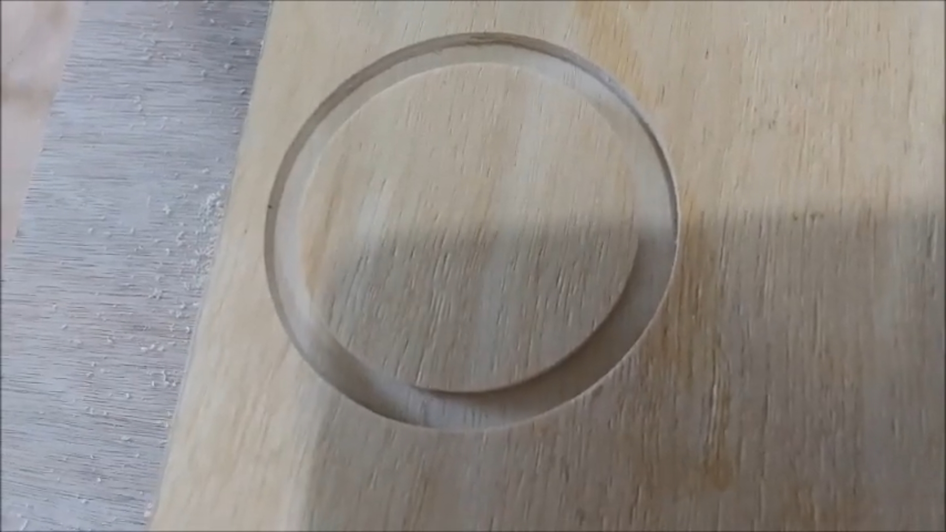 Here is a close-up shot of my last test circle. It is absolutely perfect. The diameter is right on, and there is no detectable backlash where the axes changed direction. The old Woodpile CNC
had a lot of backlash, which had to be accounted for in the motor tuning. I didn't expect the precision ball screws and nuts I am using to have much backlash. I'm glad to see they don't.
Some backlash may become apparent when I am cutting metal and can make more precise and repeatable measurements. For now in wood, the machine is working good enough.
Here is a close-up shot of my last test circle. It is absolutely perfect. The diameter is right on, and there is no detectable backlash where the axes changed direction. The old Woodpile CNC
had a lot of backlash, which had to be accounted for in the motor tuning. I didn't expect the precision ball screws and nuts I am using to have much backlash. I'm glad to see they don't.
Some backlash may become apparent when I am cutting metal and can make more precise and repeatable measurements. For now in wood, the machine is working good enough.
 So finally, here it is, the finished machine. Well finished sort of. There are a lot of things I still want to do to it in the future. The vacuum needs to be attached so it catches the chips as they
are produced. The vacuum needs to be wired in so that it will start and stop under computer control like the spindle does. I need to figure out a way to keep chips from landing on and sticking
to the grease covered ball screws, maybe bellows or sliding shields, or something. The wiring needs to be neatened up some more. The electronic box needs to be mounted on the side of the bench
below the machine and out of the way, so I can have the table back that it is sitting on. The wood x table needs to be replaced with an aluminum plate. I need a larger area of t-slot
for bolting things down. The list goes on and on. Still, the machine is done enough to have already been used on a new project. I used it to rout out a glass casting mold
that the old woodpile machine just wasn't accurate and repeatable enough to do. It worked great. I love my new CNC router.
So finally, here it is, the finished machine. Well finished sort of. There are a lot of things I still want to do to it in the future. The vacuum needs to be attached so it catches the chips as they
are produced. The vacuum needs to be wired in so that it will start and stop under computer control like the spindle does. I need to figure out a way to keep chips from landing on and sticking
to the grease covered ball screws, maybe bellows or sliding shields, or something. The wiring needs to be neatened up some more. The electronic box needs to be mounted on the side of the bench
below the machine and out of the way, so I can have the table back that it is sitting on. The wood x table needs to be replaced with an aluminum plate. I need a larger area of t-slot
for bolting things down. The list goes on and on. Still, the machine is done enough to have already been used on a new project. I used it to rout out a glass casting mold
that the old woodpile machine just wasn't accurate and repeatable enough to do. It worked great. I love my new CNC router.
If you've read this far, I hope you found this web page useful and informative, and even inspiring. I'd love it if this project inspires others to build and use their own CNC routers.
 UPDATE: Learning to write
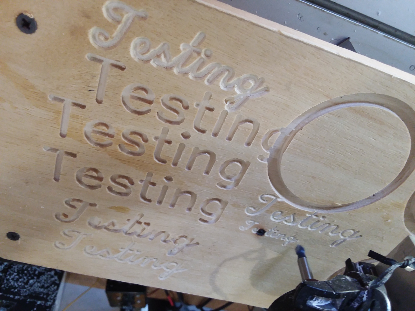
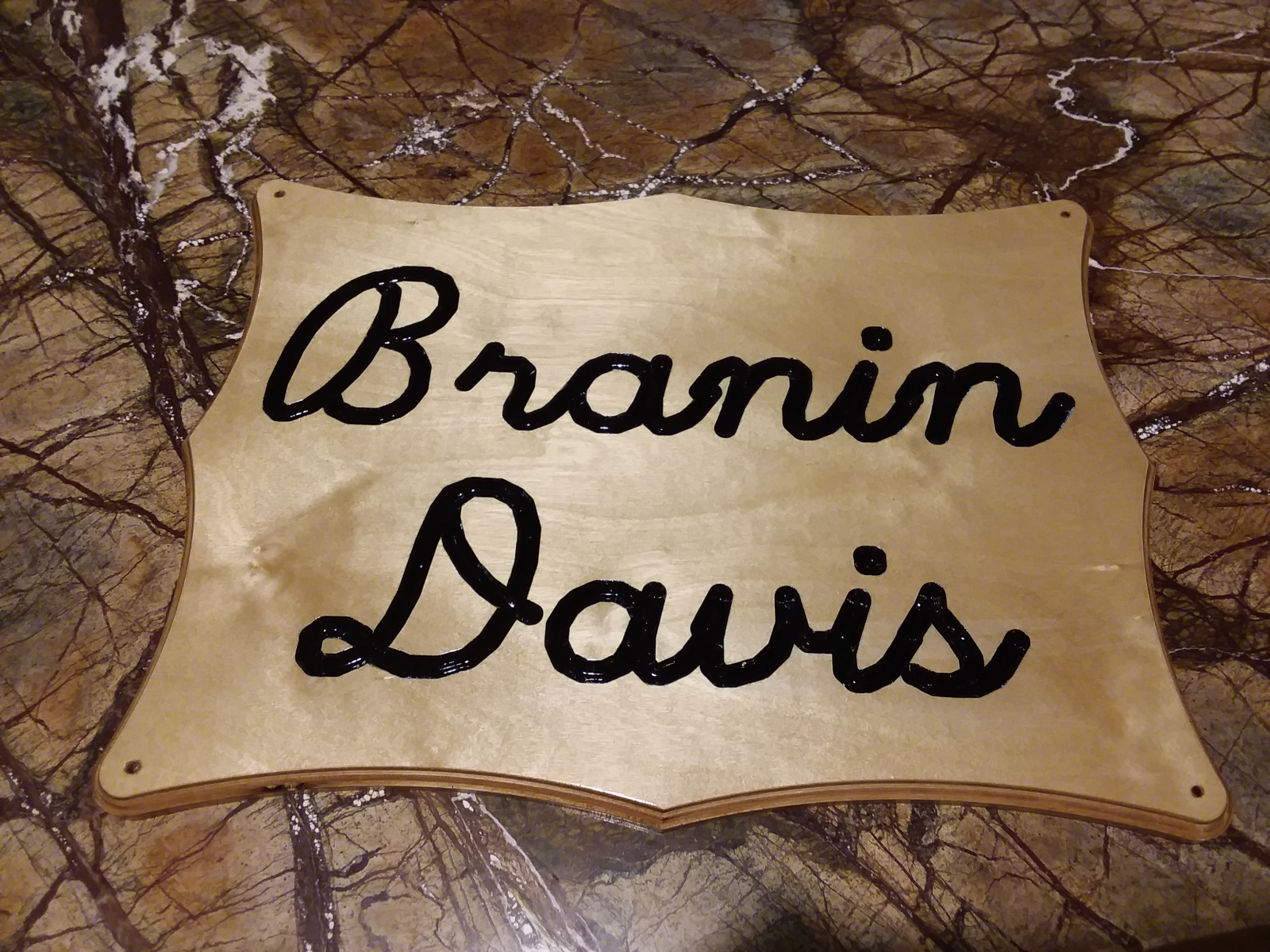
I may need to do some engraving in the future. So I practiced doing some writing on the machine with different bits, different fonts, different depths and different
speeds and feeds. I put the elevated platform
I used to initially tune the machine by cutting circles back on the X table and did some practice writing in the blank area. I've never done much engraving before.
It's good to get in the practice and figure out what works and what doesn't. The machine writes very well with the correct combinations. Maybe I'll become a sign maker.
I could start by making my own sign.
 UPDATE: The control box is mounted
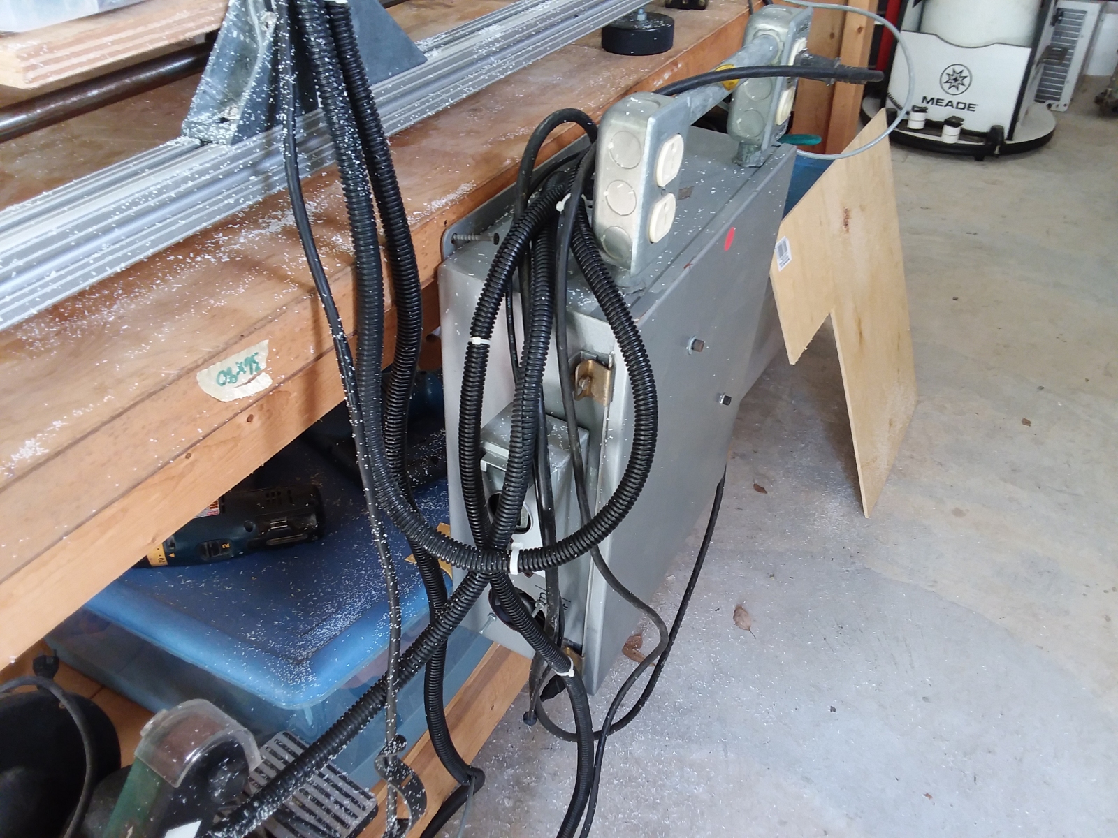
I finally got around to mounting the control box on the side of the bench supporting the machine. I had the box sitting on a small table for the longest time, so I could easily get into it to
tinker with the wiring. Well, I haven't had to tinker with the wiring for quite some time, and the box was always in the way. So I went ahead and hung it from a couple of screws on the side of the
bench. Here it is looking like Medusa with all the snakey cables coming out of the top of it. That freed up a lot of space beside the bench making it easier to move around.
 UPDATE: A major project is completed
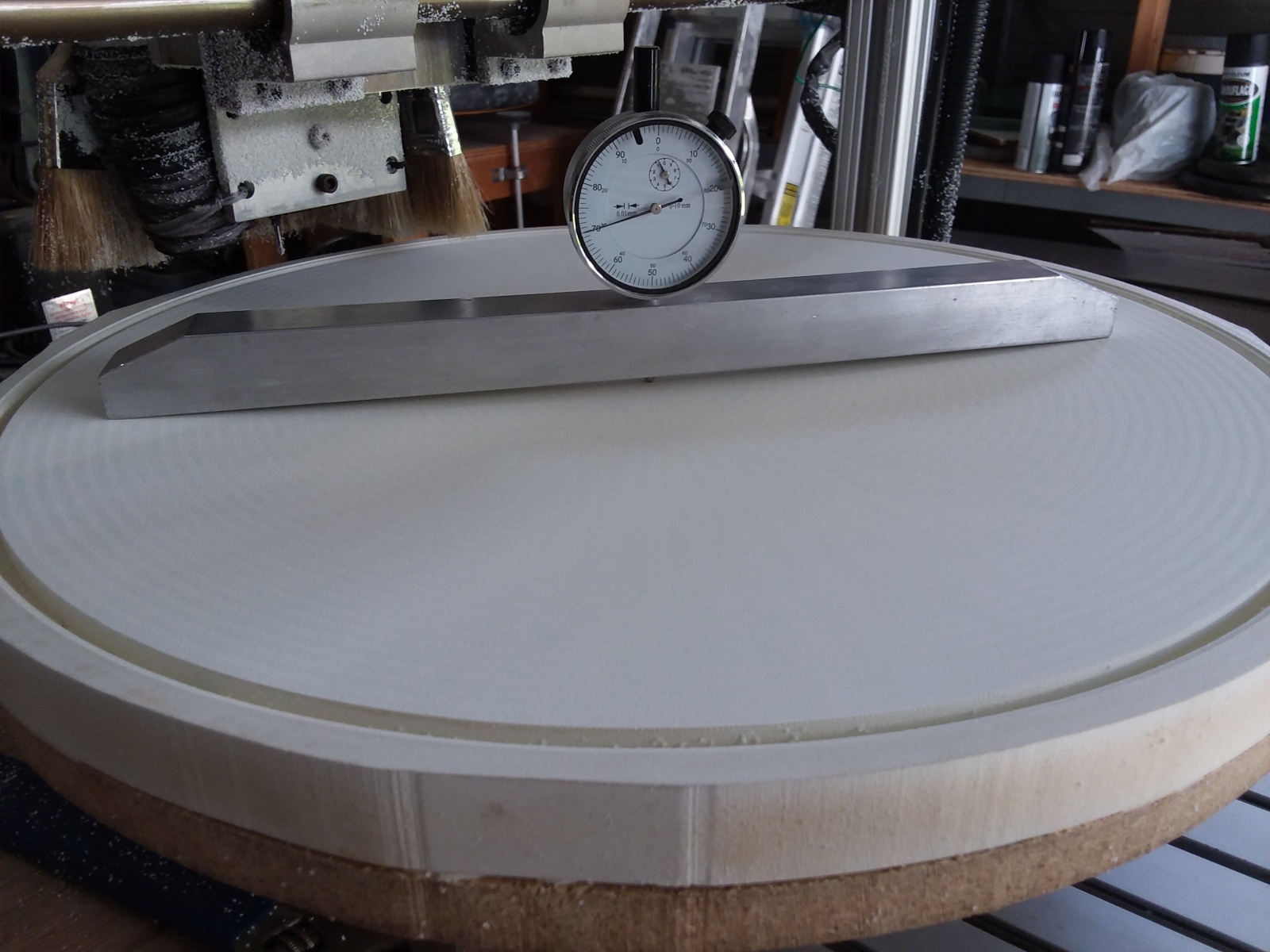
This is a photo of a master slumping mold I cut on the machine. Basically it is a big, shallow bowl 16.5 inches in diameter and cut in expanded PVC foam. The curve of the bowl has
been cut very precisely, much more precisely than I could have with any of my previous machines. This will be a master concave mold from which I will make working convex molds in
refractory plaster for slumping glass in my kilns. I will likely make a video of the entire mold-making and glass slumping process in the future. This machine works so well and is
so accurate, that even I'm surprised by it. I love this thing.
 UPDATE: A sign for the gate of our Wyoming ranch.
I carved this sign for the gate of our new Wyoming Ranch. L & M for Leslie and Mike. I used my home-made CNC router to make it. I carved the lettering with a
90 degree V bit and filled
it in with black paint. Then I covered the entire sign with several coats of satin polyurethane to make it durable and weather-resistant. It turned out really nice. I have ideas for more signs too. I put together
a web page showing how I made this sign in greater detail. Check it out.
|
Click to learn how
to meet them
|
 UPDATE: A sign for the front of our house.
The sign I made for our Wyoming ranch a while back turned out so nice that I decided to make another for the front of our house. I planned on mounting it just below the house numbers.
Looks pretty good if I do say so myself. I just love cutting stuff on my home-made CNC router.
 So here is the sign mounted on the front of the house, right below the numbers as I planned. Now the never-ending parade of delivery drivers coming to our door will know they are in the right place.
The sign is held on with four Tapcon screws. I hot-melt glued wooden plugs over the screw holes for a nice finished look. I can pop the plugs out and unscrew the sign to take it with us if we ever
sell the place and move.
So here is the sign mounted on the front of the house, right below the numbers as I planned. Now the never-ending parade of delivery drivers coming to our door will know they are in the right place.
The sign is held on with four Tapcon screws. I hot-melt glued wooden plugs over the screw holes for a nice finished look. I can pop the plugs out and unscrew the sign to take it with us if we ever
sell the place and move.
a lady to
learn how
to meet her